Help with Nucleo 144 -- no output on pins

Hi everyone. I am experiencing something strange. I moved testing my ifx007i board to Nucleo 144 due to some issues I hit with the Mega, which I’ll describe later. The board is F767ZI. This is the setup:

Using Arduino IDE. The Nucleo board runs fine, I can output on any pin, I tried with simple code. Outputs both PWM, digital, input analog, nothing out of the ordinary.

However when I build the SimpleFOC, after loading the build, the board goes mute, absolutely no response on any pin. Just to make sure, I embedded a bit of debug code to output on a pin not used by the ifx007i board, no result. I tested with the oscilloscope on all pins in case I mis-directed pins, nothing. I tried calling the pins with the Arduino names instead of addressing directly, same nothing. I am rather stumped. If you have experienced something similar, please help. Can’t think of anything at that point. I must be doing something really stupid but can’t catch it.

Below is the code.

// Open loop motor control example
#include <SimpleFOC.h>

// BLDC motor & driver instance
// BLDCMotor motor = BLDCMotor(pole pair number);
BLDCMotor motor = BLDCMotor(7);
// BLDCDriver3PWM driver = BLDCDriver3PWM(pwmA, pwmB, pwmC, Enable(optional));
BLDCDriver3PWM driver = BLDCDriver3PWM(D9, D10, D11, D3, D5, D6);

//target variable
float target_velocity = 10;

// instantiate the commander
Commander command = Commander(Serial);
void doTarget(char* cmd) { command.scalar(&target_velocity, cmd); }

void setup() {

  // driver config
  // power supply voltage [V]
  driver.voltage_power_supply = 12;
  //driver.pwm_frequency = 30000;
  driver.init();
  // link the motor and the driver
  motor.linkDriver(&driver);

  // limiting motor movements
  motor.voltage_limit = 2;   // [V]
  motor.velocity_limit = 100; // [rad/s] cca 50rpm
  // open loop control config
  motor.controller = MotionControlType::velocity_openloop;

  // init motor hardware
  motor.init();

  // add target command T
  command.add('T', doTarget, "target velocity");

  Serial.begin(115200);
  Serial.println("Motor ready!");
  Serial.println("Set target velocity [rad/s]. Example: T10 will set the target to 10 [Rad/s], T-10 will run in reverse.");
  _delay(1000);
  pinMode(D0,OUTPUT); // debug code to test Nucleo 144 / F767ZI
}

void loop() {

   digitalWrite(D0,HIGH);   delay(1); // debug code to test Nucleo 144 / F767ZI
   digitalWrite(D0,LOW);   delay(1); // debug code to test Nucleo 144 / F767ZI

  // open loop velocity movement
  // using motor.voltage_limit and motor.velocity_limit
  motor.move(target_velocity);

  // user communication
  command.run();
}
From the way you describe this problem, I think it is crashing somewhere in the setup method. I wonder if anyone has ever tested on STM32F767 before?
Could you add some printlns (or use the D0 pin-signals) to check how far you make it through the setup loop? I have a fear it could be crashing on driver.init() during the clock/timer setup.

good suggestion. i can configure the rgb leds to blink on each step and see how far it goes and take it from there.

I remember we had some issues with center aligned PWM on stm32.

You can try commenting out this line 67 in stm32_mcu.c

  1. The commenting of the center pwm line #67 didn’t help.
  2. @runger was correct. the board doesn’t go past driver.init();

I can put a few break points inside the init to at least trace the problem.

Any other ideas would be helpful.

Cheers,
Valentine

I’ve told you the wrong line actually. Try to comment out the line 39.

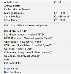
Also you can try to reduce the optimisation level. -O3 is really high code optimisation level and it can introduce strange errors.

@Antun_Skuric,

I tried both, didn’t help.

Cheers,
Valentine

Question: Where do you define the monitor_port to use?

Is this the one:

monitor_port = &print; //operate on the address of print

From memory, monitor_port is defined with
motor.useMonitor(Serial)

You could of course pass in something else e.g Serial6, or even a Bluetooth serial.

I did however it did not give init messages. I can see the messages before init.

Hi Valentine,

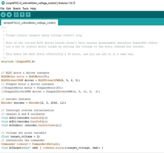
I have been running the SimpleFOC code successfully within the Arduino environment with the Nucleo 144 board (H743ZI2). I have attached the first page of the code here - my pins for the BLDCDriver are set to their default values: D9, D5, D6 with D8 as the global enable pin.

If you configure the pwm pins to their default values do you get any output? I’ve had trouble before with some STM32 boards not configuring timers correctly.

Cheers,
Nat

BLDCDriver3PWM(D9, D10, D11, D3, D5, D6)

Have you checked that D9,D10,D11 are on same timer? Btw, I tend to stick to stm32 pin naming of pins e.g PA9 in my code.

Hi Owen,

Is having all the PWM on the same timer a requisite? For my board the pins 9/5/6 map to TIM4_CH4/TIM1_CH2/TIM1_CH1 respectively - and this doesn’t (or at least hasn’t! :D) stop the board from working. Being driven by different times is just a possible cause of synchronisation issues with the PWM signal to the phases.

Best,
Nat

Having said that, I do avoid the synchronisation issue now, as I have routed the PWM phase outputs to all be on TIM1.

My board is with STM32F767ZI MPU. Yours is with H743ZI, that’s a different MPU altogether.

I tried both with default values, and called them arduino values, and in case I somehow mis-directed the pins I connected oscilloscopes to all 144 pins (that last one was a doozie). Nothing. Plus, when I run a simple PWM it does output just fine, so my conclusion is there is something sitting between me calling the PWM from simplefoc and the MPU itself. I got so frustrated I was about to toss the lab, so I’m taking it easy, and will revisit the nucleo next week. I already ordered a number of different STM board just to check what’s going on, plus I already manufactured two extra STM ones (with blank bootloaders) of my own design to test, this is really frustrating.

Also the timers should not matter, I am not touching the frequencies, though there may be something there, but I’ll chase this next week. Not all timers can be forced on the same frequency. I am not that much an expert into the silicon unfortunately, and don’t want to spend days reading docs, so I may have to ask people with skills superior to mine.

I cannot change the pins, because I am using a board which sticks on top of nucleo, unless I monkey up a rat’s nest in-between the nucleo and the driver board and start redirecting pins, but that’s just side-stepping the real problem.

@Antun_Skuric
@runger

I got some time and tried on STM32F103C8, and reproduced the init crash. It appears the pin combination must be some kind of a subset of “SimpleFOC STM32 Compatible” groups of pins else the init itself “crashes”.

For example if you have a Blue Pill,

BLDCDriver6PWM driver = BLDCDriver6PWM(PA7, PB13, PA9, PB14, PA10, PB15, PB12);

or

BLDCDriver6PWM driver = BLDCDriver6PWM(PA8, PB13, PA9, PB14, PA10, PB15, PB12);

will work, however

BLDCDriver6PWM driver = BLDCDriver6PWM(PA6, PB13, PA9, PB14, PA10, PB15, PB12);

will not go past the init.

This problem appears to be inherent to SimpleFOC only, as my sample debug code can output on random pin combinations just fine.

I am very curious what reasoning went into selecting (PA8, PB13, PA9, PB14, PA10, PB15, PB12)
in the sample code, was it just pure luck that it hit the correct working pin combination?

I have a few more STM32 MCUs, I will test my guess there too.

ON, next I tried Nucleo 144 with STM32F429ZI, exact same behavior. Apparently this issue is particular to the entire STM32 line perhaps? Without testing more boards can’t really tell however. I have couple more STM32 laying around, will check those too.

Next was 401CCU6, same behaviour. Also I spent some more time mucking with some combinations, the following

(PA7, PB13, PA8, PB14, PA9, PB15, PB12);

won’t crash the mcu however PB15 gets stuck at 100% on the oscilloscope so if you blindly connect a driver board, there will be fireworks.

I strongly suspect other pin combinations also won’t “crash” the MCU outright, but corrupt the signals on one or more pins and the driver will probably work in a severely degraded mode with the user wondering what’s wrong.

Definitely the SimpleFOC PWM initialization for STM32 hardware specific setup must be revisited and the issue if not solved at least somehow side-stepped. Using only one “lucky set” of pins on STM32 is degrading the utility of the library.

I have one more to test, G431KB (yes, the same one on the ST’s ESC1 driver).

That’s also a no-go for 6PWM. Actually the way the MCU is done, in this package even some of the default pins are not exposed so could not make it work at all. Tried to map the pins from ST’s ESC1 but two are not exposed.

These ‘init crashes’ - can be debugged in an ide like platformio. i.e. stepping through the code. Invariably it is in the code where it is trying to work out which pin map or timer to use (in HAL_ or LL_ layer). You are a bit blind without a debugger. That said getting a debugger working using stlink can be a bit challenging on some boards.