Help Hacking a cheap E-bike controller

Hi!

I’ve been working on hacking the cheapest Ebike controller I could find on Ebay.
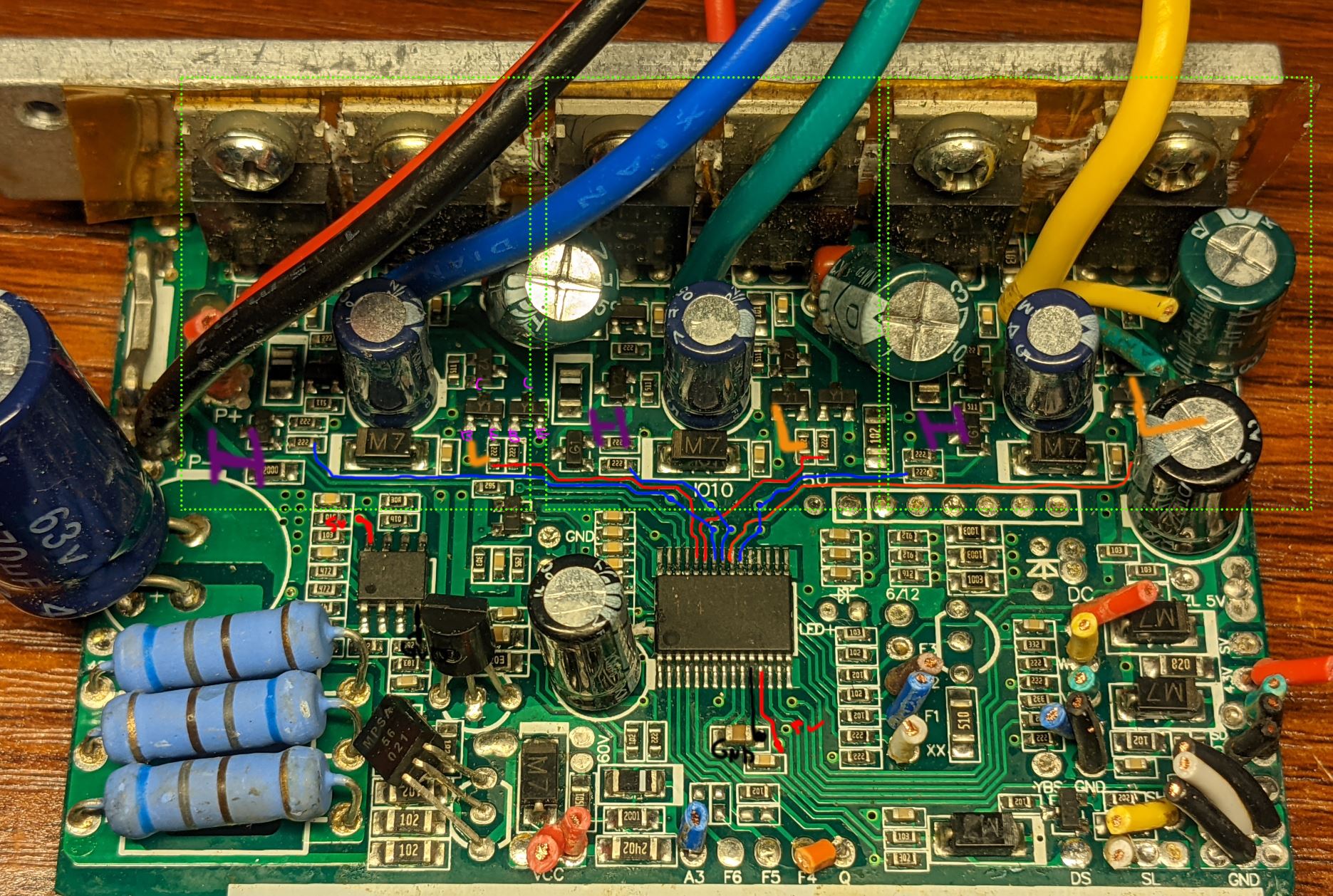
So far, I’ve taken the controller out of the housing to look at the PCB. The H/L drivers seem to be implemented discreetly instead of a single driver IC, or 3 driver ICs.

I have traced out the connections for what I believe are the 6 H/L connections to the discrete driver inputs, and 5V/GND , and removed the controller IC, soldering flywires in place of it:

I tried using the 6PWM with STM32 bluepill, and the following code:

#include <Arduino.h>

#include <SimpleFOC.h>

// Motor instance

BLDCMotor motor = BLDCMotor(7);

BLDCDriver6PWM driver = BLDCDriver6PWM(PA8, PB13, PA9, PB14, PA10, PB15, NOT_SET);

void setup() {

  // driver config

  // power supply voltage [V]

  driver.voltage_power_supply = 24;

  driver.dead_zone = 0.5f;

  driver.init();

  // link the motor and the driver

  motor.linkDriver(&driver);


  motor.controller = ControlType::velocity_openloop;

  // maximal voltage to be set to the motor

  motor.voltage_limit = 2.0f;


  // initialize motor

  motor.init();

  // align sensor and start FOC

  //motor.initFOC();

}

void loop() {

 // motor.loopFOC();

  motor.move(5.0f);

}

When powered from my lab supply w/ a current limit of ~700mA, it hits the current limit instantly. The motor I can feel is very slightly twitching, and the FETs begin to get hot. With the motor disconnected, the current limit is still reached. This indicates to me that I’m not driving the circuit correctly and thus causing the FETs to go into short.

I then thought that the issue may be the logic level being too low (3.3V instead of 5V), and I also thought maybe I’m feeding the supply too low (its a 36V/48V controller), so I switched over to an Arduino Nano w/ 6 PWM mode, and upped supply to 42V. I used the following code:
#include <Arduino.h>

#include <SimpleFOC.h>

// Motor instance

BLDCMotor motor = BLDCMotor(7);

BLDCDriver6PWM driver = BLDCDriver6PWM(5,6, 9,10, 3,11, 8);

void setup() {

  // driver config

  // power supply voltage [V]

  driver.voltage_power_supply = 42;

  driver.init();

  // link the motor and the driver

  motor.linkDriver(&driver);

  motor.controller = ControlType::velocity_openloop;

  // maximal voltage to be set to the motor

  motor.voltage_limit = 1.0f;


  // initialize motor

  motor.init();

  // align sensor and start FOC

  //motor.initFOC();

}

void loop() {

   // motor.loopFOC();

  motor.move(5.0f);

}

unfortunately, the results are identical to first try. The powersupply hits current limit immediately and cannot run the motor.
I have looked closely at the discrete driver and measured things and the implementation appears to be near identical to the somewhat well-known ‘KU63’ ebike controller. This is the schematic for the KU63 https://www.avdweb.nl/Article_files/Solarbike/Motor-controller/China-BLDC-motor-controller-36V-250W.pdf

I bought two of these controllers for if(when) I blew the one I’m modifying, but I’m thinking now I should take unmodified one and take it out of the enclosure and try to run it as-is, and probe around the controller to see if i’m missing something obvious. While I do that I thought I should make a post here seeing if any of you have any ideas about whats up. Thanks!

1 Like

You might want to check here https://avdweb.nl/solar-bike/electronics/ku63-motor-controller for details on the various hacks of the KU63. There are some links to projects where the MCU was replaced so you might find some clues in the source code for replaced MCUs.

You might also want to experiment with dead time.
Mosfet heating without load is probably caused by shoot through current.

Hey, this big board and the big mosfets can handle a lot of power… what motor have you hooked up to it?

The current drawn in your code setup will be limited only by the motor winding impedance and the voltage you set (42V!).

I would recommend trying one of two things:

  1. use a lower voltage power supply and higher ohm motors for your first tests. Something like a 10Ω Gimbal Motor will draw 2Amps at 20V, which it looks like will be no problem at all for those FETs.

  2. use software voltage limiting. Set motor.voltage_limit to 0.5V, or lower. Measure your motor’s winding resistance (just measure 1 phase to another, that value will work fine) and set the motor.voltage_limit so that the current stays below the board’s rating…

Either way you should then see some motor movement happening!

Regards,

Richard

Hi, i need your help, could you please write the ic number please.

Looking at the schematic it seems that H_in and L_in have reversed polarity.

About the IC : some unbranded mask-rom Chinese microcontroller.

found,

D79F7027 is the number. and you are right, it is a chinese microcontroller.

So, to make this work, invert 3 channels. And remember that it has 5 Volt logic levels, not 3 volts.

Is it possible to run this setup(hacked controller+simpleFoc lib) for e.bike 3 wires motor(with no hall sensors) with 6pwm steps and reading back EMF?

I just have few Lishui bldc conttoller from E.Scooters. they have Stm32f103c8. And I have made reverse schematic. I have run succesfully german opensource FOC firmware for Lishui controllers(from Pedelec-forum.de). But unfortunately with sensorless FOC I am still struggling.

Maybe someone could make me a advise, how to run just for test this library with old facioned 6step PWM commutation and back EMF closed loop.

My scooter controllers have 3 shunts on the low sides of mosfet. Voltage is 36v.
PWM phase wiring very standard for stm32: PA8,PB13 – PA9,PB14—PA10,PB15 pwm pairs.
The current sensors after OPamps go to ADCs: PA4, PA5, PA6

The mosfet drivers are IR2103s, and have deadtime already set fixed. So maybe I dont need to worry about it in the code?

Thanks for any advise how to start. I have seen some docs, but didnt find about BackEmf

Regards,
Fluctuator

Hi @Fluctuator, welcome to simplefoc!

6-step commutation and BackEMF aren’t supported (yet), at the moment we need a position sensor for closed loop control.

You should be able to get open-loop control working though, and depending on the pins exposed to the MCU there may be options to connect a sensor for closed loop.

Thanks! Nice to be here.

Is simple FOC in open loop mode better than 6step pwm with backEMF regarding to battery power consumption or heating?

It would have to be tested. At low speeds, sensor-less commutation uses open loop, so I imagine it would be the same. At high speeds, I would expect the backEMF controlled switching to be more efficient than just open loop, but I’ve never tried it out.