It should not be too hard to run these motors, resistance of around 5Ω should be quite ok to manage.
The documentation shows some examples of PID settings for gimbal motors, you can start from there. Remember to set a voltage limit and current limit for initial tests, and if possible use a power supply with current limiting. Just to be safe!
Current board uses: INFINEON IRFS7530TRLPBF MOSFET, N Channel, 60 V, 295 A along with DRV8301.
What voltage limiting would be best on these motors for a start? I assume low as possible when low resistance. Also I do not have voltage sensing on this board, would it be fine with encoder only to run close loop foc mode?
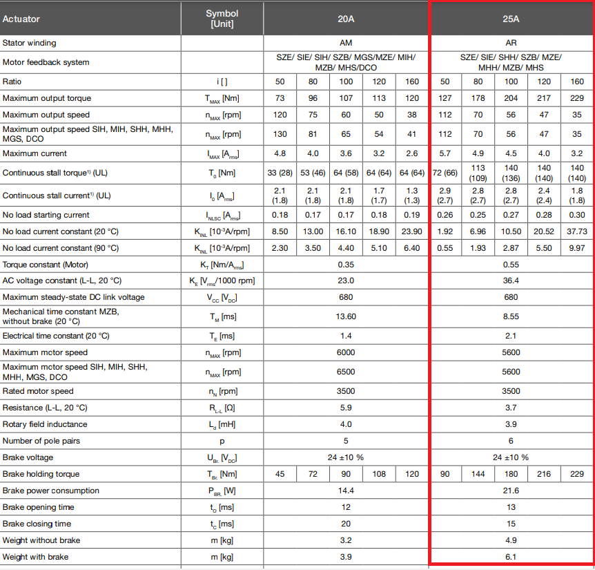
Your FETs look very powerful, and the resistance of the motor is not so low with 3.7Ω. So I think you will be perfectly safe testing with 12V, or even probably 24V using these FETs.
Lets assume some software error causes DC current to be switched on through the motor windings - in this case 24V/3.7Ω = 6.5A - seems like the FETs can handle this, and its also within the motor’s maximum range. Of course, you can’t leave it switched on like this, but you will have some seconds to switch things off before it all burns up
Yes, this will be fine. I don’t think voltage or current sensing will be necessary for this motor, it should work fine in closed loop using just a position sensor.