For those of you who have some insight, I’d like to ask if you know / guess what is the function of these hall sensors on a hoverboard motor.
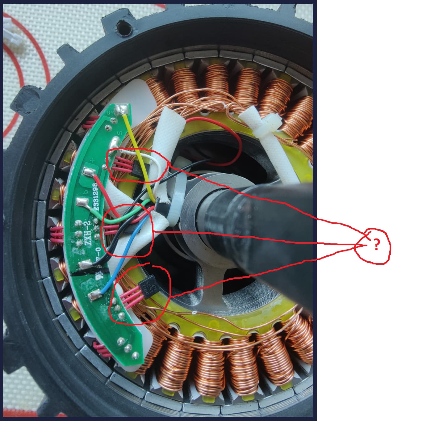
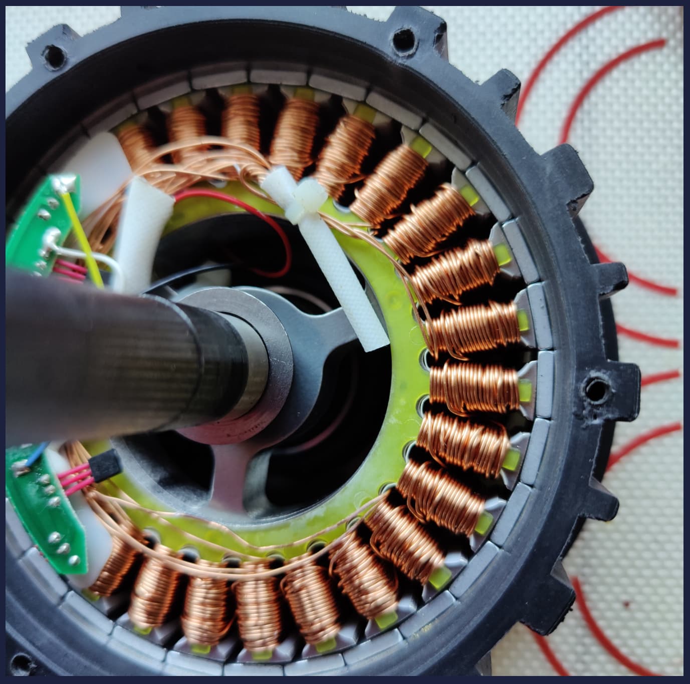
It’s a Jetson hoverboard. There are three halls on the inside, which are obvious. However, I see three more pointing inwards towards the motor shaft, apparently doing nothing. Any of you have any idea what are these for?
I’d expect there to be a magnet mounted to the axle, so the inwards facing halls could measure the orientation of the board vs. the wheels…
But maybe it is a case of a sensor board design being used on multiple models of hoverboard, with not always the same configuration in terms of which parts are used?
Strange indeed. It doesn’t looks like they’re positioned accurately enough to do anything useful even if there were signal lines for them and a magnet to sense.
Short answer yes, I’ve done it. Long answer – mechanically it’s really difficult, since the wheel is single pivot and you have no reference to put the magnet. So, what I did, was I came up with two solutions.
Placed a second pivot by literally gluing (or bolting) the pivot to the face of the hoverboard. Requires also ball-bearings, etc.
Designed from scratch (used a professional CAD program and made the parts from laser-sintered steel) and manufactured a very complex throughhole gearbox which goes on the back of the hoverboard and has inside a custom designed AS5047P PCB to hold the sensor. This requires microscopic ball-bearings and very fine motor skills and very high level of precision.
I don’t have the pictures handy to post here but you get the idea. Let me know if you want pics.
One thing I’ve been wanting to try is to replace the 3 digital halls with linear halls and see what sort of signals you get. They might be too saturated by proximity to the magnets, but hopefully two of the three would give good midway signals at any given time and could be transformed into an angle. I’ve got a bunch of 49E linear halls, so if anyone wants to take on the task let me know and I’ll mail you some.