Hello everyone, I am having problems controlling a BLDC motor. Specifically, when I checked the hallsensor, I found it was not working. Below is the code I use: #include <SimpleFOC.h>
// #include <PciManager.h>
// #include <PciListenerImp.h>
void loop() {
// IMPORTANT
// read sensor and update the internal variables
sensor.update();
// display the angle and the angular velocity to the terminal
Serial.print(sensor.getAngle());
Serial.print(“\t”);
Serial.println(sensor.getVelocity());
delay(100);
Do you actually have external pullups? A strong pull up resistor on each hall might be required for the halls to work, e.g. for hoverboard motors you might need a 1.5k resistor pulling up to 3.3v.
The internall pullup resistors are typically weak e.g. 30K ohms or more.
You might find that using input_pullup will work when the motor isn’t running (i.e. turning the motor by hand), but when you start the motor (which introduces noise) you get a lot of ghost interrupts - which gives glitchy velocity. So using an external pullup of 1 to 5K ohms will ensure a nice step transition as each hall passes through the magnetic fields of the permanent magnets of the rotor. If you have a 11pp motor then you’ll have 22 pole transitions which each hall can detect. So there should be 66 interrupts per rotation. If there is noise from the motor you can some times see 100s or 1000s of false interrupts happening. A strong pull up (e.g. a lower 1.5K resistor attached between 3.3v and each hall) will ensure that you get nice steps.
The motor I use has 15 pairs of poles, the pull-up resistor I use is 10k ohms. When the wheel rotates, it jerks. Is it because my PID parameters are not appropriate or due to some other reason?
motor.PID_velocity.P = 0.3f;
motor.PID_velocity.I = 0.3f;
motor.PID_velocity.limit = 0.04f;
Are you seeing stable/correct angles when you turn the motor? Are the angles correct i.e 1 rotation = 2pi?
Those pullups (at 10k) are still a bit weak, and may be prone to noise. For hoverboard motor halls i found 10k to glitch when motor was running and settled on 1.5k.
In terms of tuning, I’d start with zero for I and D and slowly increase P. You should initially see the motor speed lagging what you ask for and then when you find a value of P that gets close to your desired speed (70%) you might start to see speed wobbles. Only then would i play with D (to dampen wobbles) and i (to remove steady state error).
Note the d term is often a small value, much less than 1
hello,
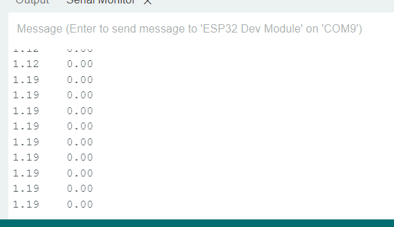
When I control using closeloop, I set the velocity to 5 rad/s, then change the PID parameters. Initially I gave I = 0 then changed P. I realized at motor.PID_velocity.P = 0.2; The motor started to accelerate but I noticed on the serial screen that the voltage gradually increased to 1 value and the wheel stopped rotating.
When tested with higher P values, the wheel rotates unevenly. It seems like it only rotates for a while and then spins again, causing the wheel to jerk.
Below is a picture of the voltage in the second column. When the voltage is < 0.8, the wheel still rotates, but when it is greater than 0.8V, the wheel stops.
I use esp32S3.
lets keep the conversation to one thread, if possible, otherwise people will have trouble following your problem and you will get less help.
From the way you describe the problem, I would say you are losing track of the motor’s position - something is not working right with your hall sensors.
Are you powering them from 5V or 3.3V? Have you looked at the signals from the HallSensor with an oscilloscope, and do you get a good signal, or is there maybe a problem with the voltage when the problem occurs?
When you run the motor in torque-voltage mode (no PID for velocity), does it run well? Can you run it at voltages >1V in torque voltage mode?
From the sounds of things, I think you will need some debugging equipment to solve the problem.
But for sure you should try the simpler examples first:
sensor test code - to make sure the sensor is working correctly - you can print the angles to the console, and check the sensor is returning 2PI (6.28) for a full revolution of the motor when you turn it by hand
torque voltage mode - make sure this is working well before you try any PID tuning
if the sensor is working by hand but not working well when the motor is powered then it is probably an electrical problem with the hall sensors or the power supply. Then you will need some debugging equipment like a scope to look for the problems.
Thank you, but I think the variable doesn’t work well when powered. I took this motor from the slider and I used the DRV8302 with the Esp32S3 to connect, it seems like I’m missing something.