Hi everyone,
I would like to share some progress on the custom BLDC motor (and driver) that I’ve been working on for past few months. From the last version (discussed here) there were a few major changes.
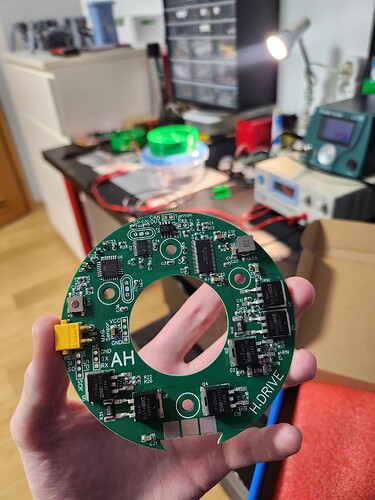
First of all, a completely new driver board replaced the old ugly squared shaped one :D. The new board is based around the same schematic as the previous one with some minor updates mainly in the microprocessor part.
As always even the new board has some issues. I burned one because of insufficient trace width on some parts. For now it is fixed with some temporary wires soldered here and there ![]() .
.
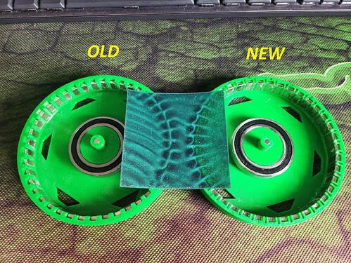
Now to the more important change and topic of this question/post. I have rebuilt the motor a little ( quite a lot ![]() ). The largest “improvement” is addition of halbach magnetic array to the rotor.
). The largest “improvement” is addition of halbach magnetic array to the rotor.
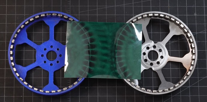
While inspecting with the magnetic flux foil the halbach arrangement seems to “work”, since the magnetic field is stronger on the inner side of the rotor and weaker on the other one. I’ve also checked the polarity of the magnets with hall sensor (seems right).
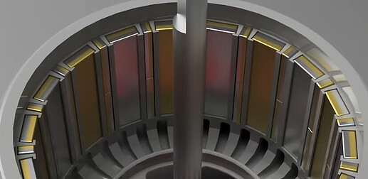
As a reference for placing the magnets I’ve used this picture from Christoph Laimer’s video.
The “only problem” is that the new rotor doesn’t work ![]() . The setup is perfectly functional with the standard rotor, but as soon as I put the halbach one on, it won’t even pass the sensor alignment process.
. The setup is perfectly functional with the standard rotor, but as soon as I put the halbach one on, it won’t even pass the sensor alignment process.
The video shows the setup equiped with the halbach rotor. It makes very little movement while aligning the sensor and than just says MOT: Failed to notice movement.
Increasing the max allowed voltage with both
motor.voltage_sensor_alignmotor.voltage_limit
only makes more current flow but creates no noticeable difference in movement.
Side notes:
The rotors have different pole count, but I have reflected that in the code.
Halbach - 40 poles (40 main magnets + 40 additional 90° rotated magnets)
Normal - 42 polesMagnets in halbach rotor are stronger by themselves (N42 vs N35). And the difference in magnetic strength is very noticeable.
I increased the max allowed voltage up to the point, where at 3.5A flowing during alignment phase the motor did not make any improvment in movement.
I am testing the setup in torque voltage mode. My sensor is AS5600 I2C magnetic encoder.
Does anyone have clue why this might be happening?
Thanks and Happy New Year to everyone ![]() !
!
Adam


