Thanks for finally getting to the bottom of it! I ran +V lines under the NC pin in a couple places on my old designs, so they wouldn’t be possible to fix with bodge wires. But it’s good to know the mosfets I’ve pulled from GooserCS boards are usable if I ever make a design with the external drain-source connection.
I really appreciate it when companies are looking out for us like this. Such forward thinking cost cutting measures as these make their products cheaper for the customer. I think other companies should take notice and also reuse their part numbers for different chips.
1 Like
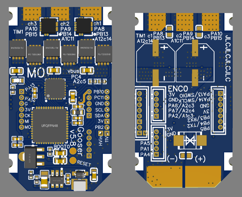
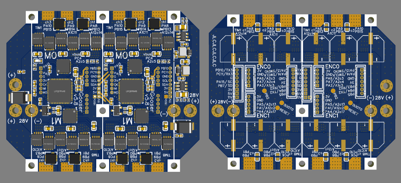
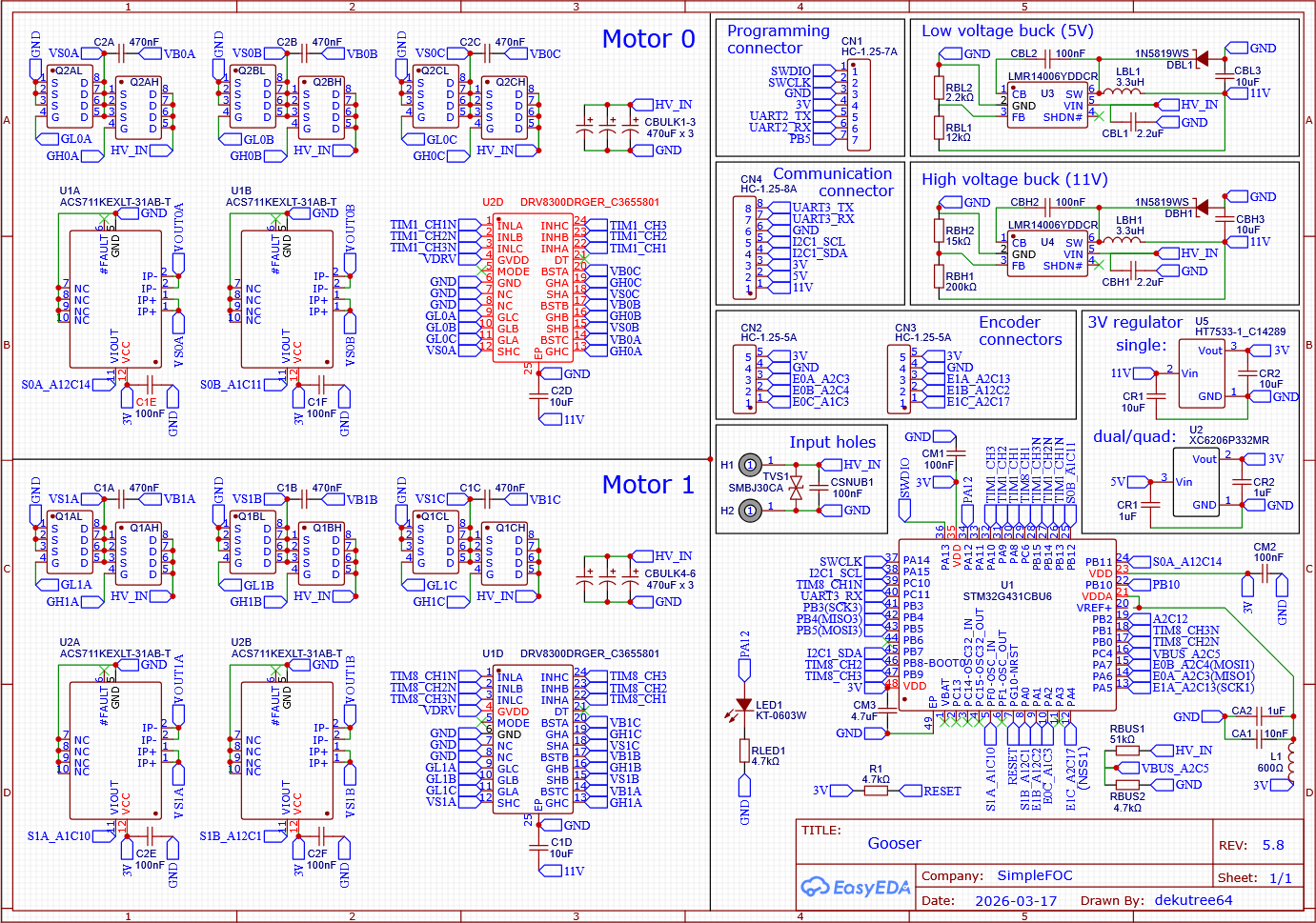
At last it’s complete! This is hopefully the final incarnation of Gooser.
I decided to retain v5.7 as a separate project and create a new one for v5.8. The v5.7 URL is gooser4_copy, which always annoyed me ![]()
- Increased the width of the tileable area by 1mm because Infineon mosfets were really crammed together (fine for hand assembly, but probably too tight for a machine)
- Changed mosfets to BSZ0500 (BSZ0901 runs much cooler than JMSL0302, but is NRND and this looks to be Infineon’s replacement for it)
- Changed the aux pin header to a proper communication connector
- Added more GPIO and reworked pins to give more SPI and UART options
- Added an LED controlled by PA12
- Changed HV buck to use the same IC and inductor as LV buck, reducing cost and board size
- Removed LV buck on single-motor version, and moved HV buck so it doesn’t increase board width
- Reverted to the smaller 3V regulator, except on the single-motor version
- Renamed VDRV and LVin to 11V and 5V
- Renamed the phase A,B,C order because the old way was confusing
- Shuffled the encoder pins to work nicely with STM32HWEncoder
- No more large exposed areas for copper bars. Just pads for SMD electrolytics, and alternative pads for soldering through-hole type electrolytics sticking off the side of the board (easier than SMD).
- Single-motor no longer has power input holes. Instead I’ve modified the bottom layer copper areas so the left half is HV_IN, allowing wires to be soldered to the board at the bottom edge like a typical ESC.
A few months ago I succumbed to peer pressure and made a version with CAN transceiver. It was a terrible struggle to squeeze it in, and even after achieving victory, I found that I wasn’t happy. What it really needed was more GPIO, and the CAN pins can’t be used for anything else. Besides, CAN is not much benefit for a design like Gooser where all the drivers are located near the battery, so I repurposed its two pins and added one more to the programming connector as well. I could have added two, but that would make the programming and communication connectors look identical, which opens up the possibility to accidentally plug a cable into the wrong one and fry something with the 11V and 5V pins.
When I tried using two SPI encoders on my CNC, it was confusing getting them both connected to the shared SPI pins among the two encoder connectors. Now there are two alternatives: One encoder utilizing both encoder connectors and the other on the programming connector, or both on the programming connector (which would still involve making a splitter cable, but a less confusing one than before). You do have to configure SWDIO and/or SWCLK as GPIO, and thus use the reset touchpad for programming, but that’s not such a big deal.
Having a second UART interface on the communication connector means you can still configure and debug it while the programming connector is in use by encoders.
3 Likes