Gooser: a 4-in-1 Lepton derivative

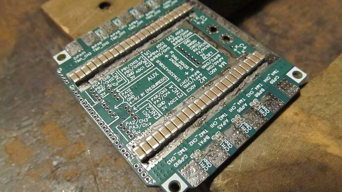
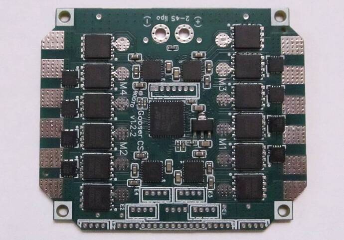
The boards have arrived! But the capacitors and connectors from LCSC may not be here for another week, so I can’t do any testing yet.

Nonetheless I have been preemptively writing the firmware. The most amusing problem I’ve discovered is that I should have called the motors M0-M3 instead of M1-M4, since the code is naturally zero-based. But I think it’s too much hassle to change at this point, since I’d want to rename all hall sensor and current sensor nets to match.

I found one minor hardware problem. I assumed there would only be one 100nF 0402 capacitor on the JLC basic parts list and used the first one I saw, but it turns it was only rated for 16V. Only the input snubber is exposed to high voltage, so that’s no problem to swap out on my boards while I’m soldering the ones on the back, and I’ve switched them all to the 50V version in EasyEDA.

The ADC configuration was fun. It’s much easier if you read the reference manual (rm0440 for this chip) to see how the hardware works rather than trying to understand it from the library interface. On Lepton I got so mad at the hideously cluttered LL and HAL libraries that I just wrote my own register #defines, but actually the official #defines for direct register access are reasonably well done so I’m using them this time. The DMA section of the manual is not entirely clear on how to set up for auto-triggering by ADC, so hopefully I did it right.

The general approach is to start the sampling for the next motor just before updating the current motor, so the next motor’s update will have recently-measured data ready to go without any waiting for the ADC. The ADC data is read by DMA into a circular array and then sorted out by using the pin numbers in the InlineCurrentSense and LinearHall classes as indices into that array.

/*
Current sense pins, phase A,B
M1 PB14 PB12 adc1 ch 5 11
M2 PF1 PA4   adc2 ch 10 17
M3 PB11 PB15 adc2 ch 14 15
M4 PA0 PF0   adc1 ch 1 10

Encoder pins
M1 PC4 PB2 adc2 ch 5 12
M2 PA2 PA3 adc1 ch 3 4
M3 PB1 PB0 adc1 ch 12 15
M4 PA6 PA7 adc2 ch 3 4
*/
LinearHall sensor[4] = {
  // Pin numbers are actually are indices into adcData[] (see ReadLinearHalls and ADC sequence config)
  LinearHall(3, 1, 6),
  LinearHall(4, 6, 7),
  LinearHall(10, 8, 7),
  LinearHall(13, 15, 7)
};
InlineCurrentSense currentSense[4] = {
  // Pin numbers are actually indices into adcData[] (see _readADCVoltageInline and ADC sequence config)
  InlineCurrentSense(15.0f/3.3f, 1.0f, 0, 2), // M1 and M2 have 15 amp sensors
  InlineCurrentSense(15.0f/3.3f, 1.0f, 5, 7),
  InlineCurrentSense(31.0f/3.3f, 1.0f, 9, 11), // M3 and M4 have 31 amp sensors
  InlineCurrentSense(31.0f/3.3f, 1.0f, 12, 14)
};

volatile uint16_t adcData[16];

void ReadLinearHalls(int hallA, int hallB, int *a, int *b) {
  *a = adcData[hallA];
  *b = adcData[hallB];
}

float _readADCVoltageInline(const int pin, const void*) {
  return adcData[pin] * (3.3f/16384.0f);
}

void setup() {
  RCC->AHB1ENR |= RCC_AHB1ENR_DMAMUX1EN | RCC_AHB1ENR_DMA1EN;
  RCC->AHB2ENR |= RCC_AHB2ENR_ADC12EN;
  RCC->CCIPR |= RCC_CCIPR_ADC12SEL_0; // ADC use PLL clock
  ADC1->CR = ADC2->CR = ADC_CR_ADVREGEN; // Enable voltage regulator
  delayMicroseconds(20); // Voltage regulator startup time from STM32G431 datasheet

  // Configure ADC to read one motor's halls and current sense per trigger event
  ADC12_COMMON->CCR = 6 | ADC_CCR_MDMA_1 | ADC_CCR_DMACFG; // Dual mode regular simultaneous, enable DMA (2 bytes per sample, circular)
  ADC1->CR = ADC2->CR = ADC_CR_ADEN | ADC_CR_ADVREGEN;
  ADC1->CFGR = ADC_CFGR_DISCEN | (ADC_CFGR_DISCNUM_0); // Each ADC reads two values per trigger
  ADC1->CFGR2 = ADC_CFGR2_ROVSE | ADC_CFGR2_OVSR_1; // 4x oversample, giving 0-16384 range
  #define ADCSQ(idx, ch) ((ch) << ((idx)*6)) // More concise than the ADC_SQRx_SQy #defines
  // Note: SQR1 low bits specify the number of conversions
  // Note: ADC1 and ADC2 can't convert the same channel number at the same time
  ADC1->SQR1 = 8 | ADCSQ(1,5) | ADCSQ(2,11) | ADCSQ(3,1) | ADCSQ(4,10); // M1,M4 current
  ADC1->SQR2 = ADCSQ(0,3) | ADCSQ(1,4) | ADCSQ(2,15) | ADCSQ(3,12); // M2,M3 hall
  ADC2->SQR1 = 8 | ADCSQ(1,11) | ADCSQ(2,5) | ADCSQ(3,3) | ADCSQ(4,4); // M1,M4 hall
  ADC2->SQR2 = ADCSQ(0,10) | ADCSQ(1,17) | ADCSQ(2,14) | ADCSQ(3,15); // M2,M3 current
  DMA1_Channel1->CCR = DMA_CCR_CIRC | DMA_CCR_MINC | DMA_CCR_PSIZE_1 | DMA_CCR_MSIZE_1;
  DMA1_Channel1->CNDTR = sizeof(adcData)/4;
  DMA1_Channel1->CPAR = (uint32_t)&ADC12_COMMON->CDR;
  DMA1_Channel1->CMAR = (uint32_t)&adcData;
  DMAMUX1->CCR = 5; // ADC1 (reference manual RM0440, page 420, table 91)
  ADC1->CR = ADC_CR_ADSTART;
...
}

void loop() {
  for (int i = 0; i < 4; i++) {
    while(!(ADC1->ISR & ADC2->ISR & ADC_ISR_ADRDY)){} // Make sure this motor's hall and current sense values are ready
    ADC1->CR = ADC_CR_ADSTART; // Start ADC for next motor
    motor[i].loopFOC();
    motor[i].move();
  }
}

Although I’ll need to use a different configuration during calibration since I won’t be able to keep requesting conversions during that. I think just setting ADC1->CFGR = ADC_CFGR_CONT will do it. That should loop through the whole sequence as quickly as possible until told to stop.
2 Likes

Hi,
would it be OK to use only three motors, or will your ADC sampling be hardcoded?
I still hope I could run two motors on one shaft, but that’s probably too difficult. (four motors but three sensors, NAH )
(calling motor.move can only be done for one motor at a time for now?)

Of course you can use fewer than 4 motors. As-is it will waste a few microseconds sampling the pins for the unused motors, but unless you want to use those pins as digital I/O then there’s no real need to change the ADC configuration.

Although come to think of it, one of my “stretch goals” was to make SPI available using the hall pins of two motors. I forgot about it and only SPI1 MISO/MOSI are available on M4. SPI3 MISO/SCK are available on the UART pins, but no complete sets anywhere. Not a problem for me, but sad that it limits other potential uses for the board.

Not sure what you mean by this? The main loop is calling move on all 4 motors.

For your dual-motor idea, I think you’d initialize both drivers but leave the second BLDCMotor unused. Then call driver->setPwm(Ua, Ub, Uc); on the second driver using the voltages from the active motor. Or if the two motors aren’t perfectly synchronized, then you could update the first one like normal, call linkDriver with the second driver, call setPhaseVoltage again but with an offset applied to the electrical angle, and then link back to the first driver.

1 Like

That’s my concern: each motor has it’s own line
motor1.move(target1)
motor2.move(target1) (same target for dual motor axis)
…then the next motor.
There is always a small delay between two hard-coupled motors.

I doubt the delay would be a problem when the motors are only mechanically connected. Most of the time you’ll be advancing the stator field in the direction the motor is moving, so if one stator is lagging a few electrical degrees behind for a few microseconds between the setPwm calls, it will just be contributing less torque, but not fighting against the other. I don’t think you’d want to run angle/velocity PID on them separately or they really could fight eachother, so you will need to customize the main loop for this application.

Connecting a single motor to two drivers would be much more difficult. You’d have to get the timers synchronized within ~100ns or there would be times where the two drivers have opposite mosfets on and short out.

1 Like

Looks good, so you plan to drive all motors, are you expecting 4 pwm inputs coming to the mcu!!. I have a use-case where i intend to receive 4 pwm inputs and drive 4 bldc motors.
I was thinking of using STSPIN32G4 + DRV8300 to drive 2 bldc motors and then another set of STSPIN32G4+ DRV8300 to drive another set of motors.
Looking at your Design it seems G4 is capable of driving all 4 motors in 1 go.
BTW from firmware point of view for a single motor pwm input + bmef monotoring + VBAT_sense is what i would be monitoring.

I considered STSPIN32G4+DRV8300 as well, but gave up pretty early in the PCB layout process. It was looking like the per-motor board size would be significantly larger than Gooser. It would have significantly higher voltage rating to make up for it, but I don’t need it.

I have made some more progress. No spinning yet, but all appears to be well so far.

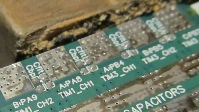
Soldering the capacitors on the back took a couple hours. I used a toothpick to apply paste, tweezers to pick up the tiny things, and a needle to nudge them precisely into place.


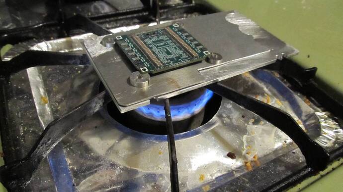
Then place them on whatever scraps of aluminum I had lying around, and cook them until the solder turns shiny. I should have gotten it better centered because the aluminum hanging off the side of the burner seemed to be wicking heat away.

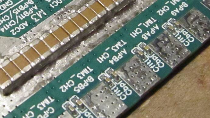
I’d say I got a touch too much solder on the small capacitors and a touch too little on the large ones, but good result overall.

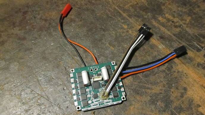
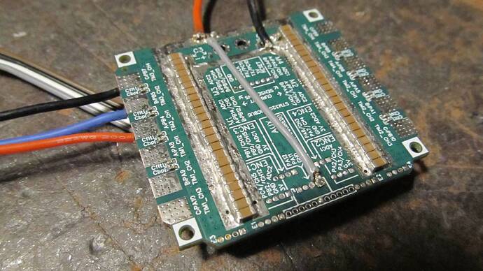
Then add the programming connector, some temporary battery/motor/encoder wires (and a jumper wire to the 3V regulator input, which is fine when only running one motor’s worth of hall sensors), and a couple 820uF capacitors. None on M1 and M2 because I need clear access to all the encoder solder pads there. This board will be running two 2208 motors and two tiny 1404 motors, so 2146uF total is probably enough.


I made a terrible mistake, getting solder on one of the holes for the board-to-board connector along the edge :slight_smile: That will be a pain to get opened back up so I can solder the pins. I filled all the other holes intentionally since I’ll be soldering wires flat to them.

Software-wise, so far I only have it communicating over UART. I had to program the boot bits, but did not need the BOOT0 touch pad (which is good since I didn’t have room for it on the buck converter version). Correct configuration is nSWBOOT=0, nBOOT0=1, to boot from main flash memory.

It crashes if more than two drivers are initialized. I think it’s a limitation of SimpleFOC’s timer pin configuration code. I’ll have to go digging tomorrow to find out how to bypass that and set them up directly.

EDIT: It’s a heisenbug. It crashes somewhere in the recursive function findBestTimerCombination, but if I try to track down the exact location of the crash by peppering the code with Serial.print calls with delays after them to make sure the text gets to the monitor, all 4 drivers initialize just fine.

I don’t see any reason why it shouldn’t work. SIMPLEFOC_STM32_MAX_PINTIMERSUSED is 12, which is how many I need. And according to the printout, it never gets more than a few levels deep on the recursion, so no stack overflow.

EDIT2: At long last, I’ve found it!

int scoreCombination(int numPins, PinMap* pinTimers[]) {
  // check already used - TODO move this to outer loop also...
  for (int i=0; i<numTimerPinsUsed; i++) {
    if (pinTimers[i]->peripheral == timerPinsUsed[i]->peripheral
        && STM_PIN_CHANNEL(pinTimers[i]->function) == STM_PIN_CHANNEL(timerPinsUsed[i]->function))
      return -2; // bad combination - timer channel already used
  }
  ...

pinTimers[i] reads off the end of the array. It only has 3 entries for 3PWM, whereas i goes up to 11 with 4 motors. Off to github to make a report…

1 Like

I quite like your hightech reflow plate setup.

I’ll have to try that to see if I can swap the FETs on one of my dead qvadran boards.