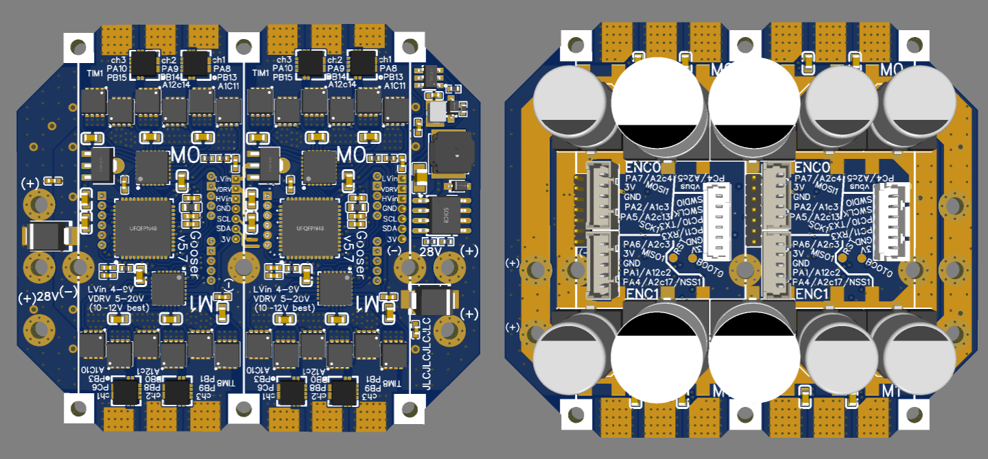
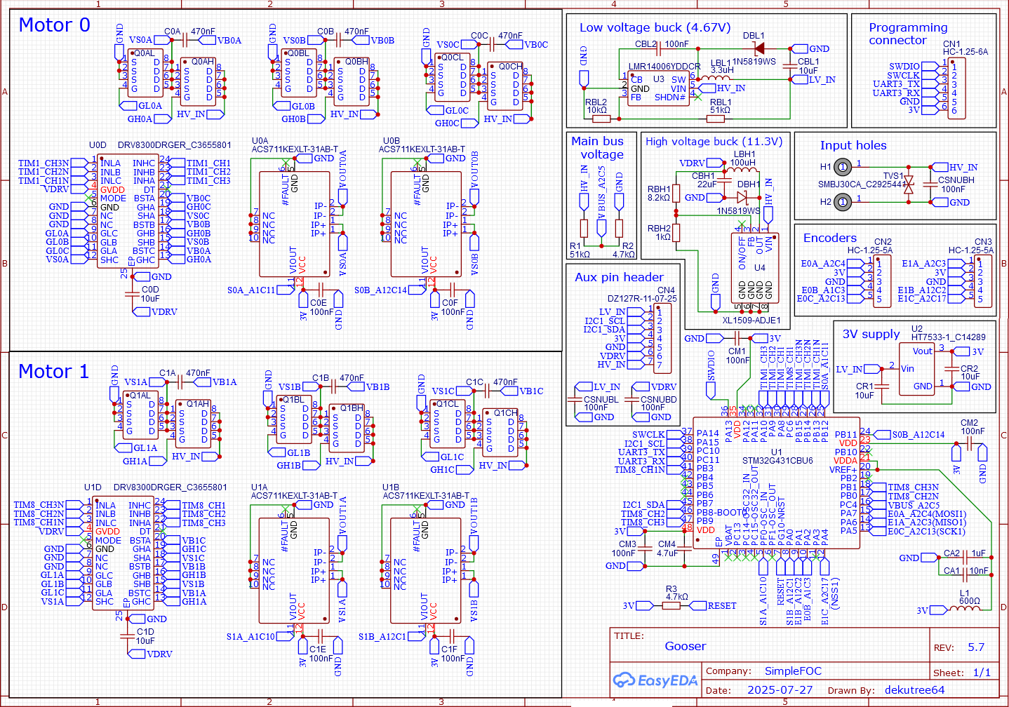
Now that I’ve done some real-world testing with Gooser5, I could see where it needed a few improvements.
- Changed to 2 channel current sense instead of 3, as I had considered back in post #85. Minimal difference in testing, and this way is $1 cheaper per motor, simpler ADC code, and the mounting holes can be spaced 46mm and board size reduced by 4mm.
- Switched around some ADC channels so both motors use ADC1 for phase A and ADC2 for phase B (simplifies ADC code).
- Renamed the phases so they match the timer 1,2,3 pin order rather than the DRV8300’s phase names (initializing the driver was unnecessarily confusing).
- Changed to 0603 capacitors on the back for the current sensors, for easier hand soldering.
- Moved reset pullup to top layer.
And of course once I got started I changed a bunch of other stuff too.
- Changed mosfets from BSZ0901NS to JMSL0302AU. Saves about $3 per motor, and BSZ is not recommended for new designs, and doesn’t really have any advantage aside from brand reputation.
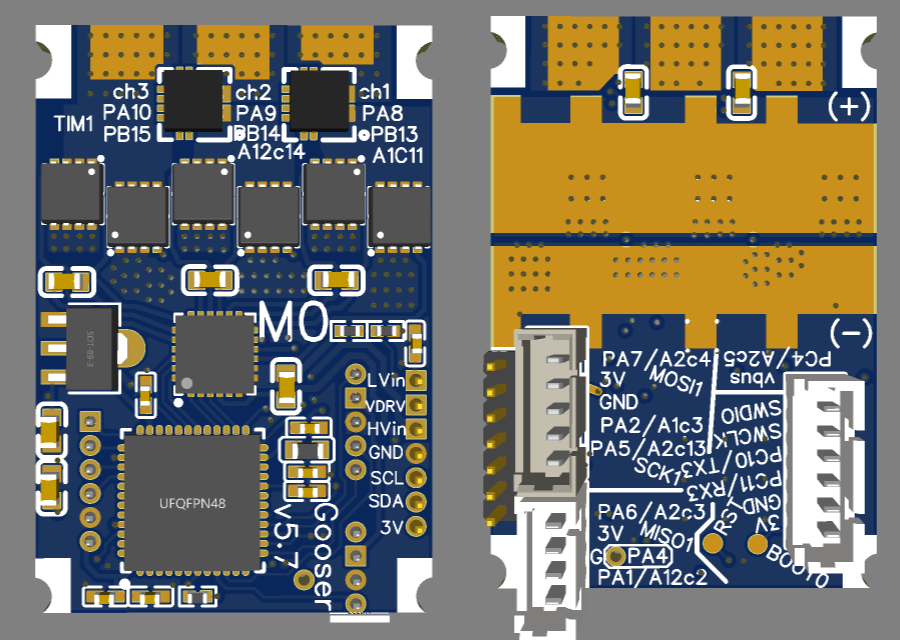
- Added an exposed copper trace connecting 3V to the encoder connector power pins. This can be cut and and solder a wire to LVin to give higher voltage on the connectors for digital hall sensors.
- Changed low-voltage buck to output 4.67V instead of 4.3V so it can supply digital halls.
- Changed to the larger 3V regulator from Lepton, which eliminates the need for the low-voltage buck for single-motor, though it comes at the cost of not being able to properly mount the programming connector on the top side (it will still work, just tilted up on the edge of the CPU).
- Rearranged the aux connector so LVin can be joined to VDRV easily, and to solve a problem where HVin would get disconnected on minimum width single-motor boards.
- Expanded the exposed copper areas to make SMD electrolytic capacitors fit better. This eats into the documentation area, so I had to move the timer pin numbers to the top silkscreen.
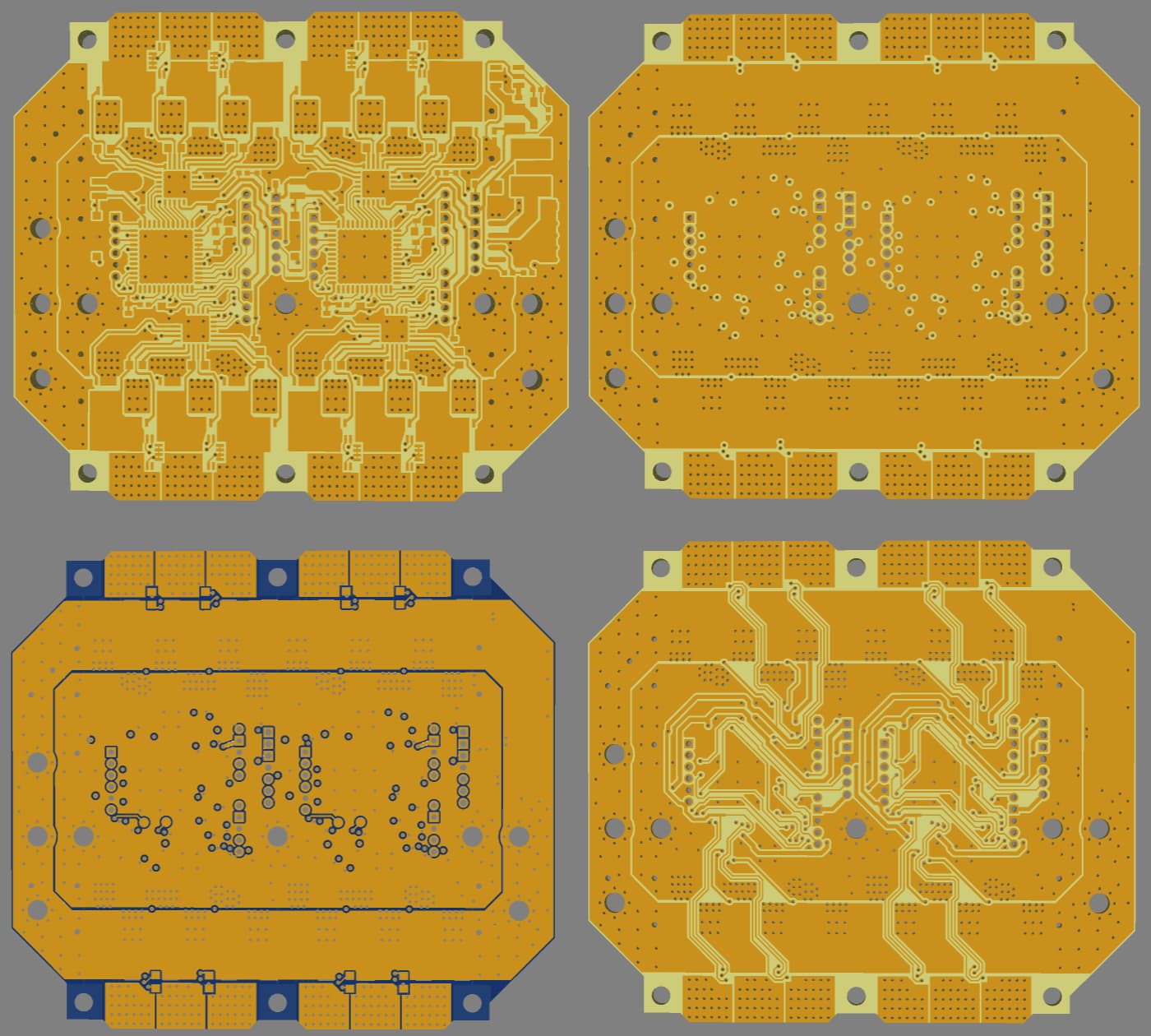
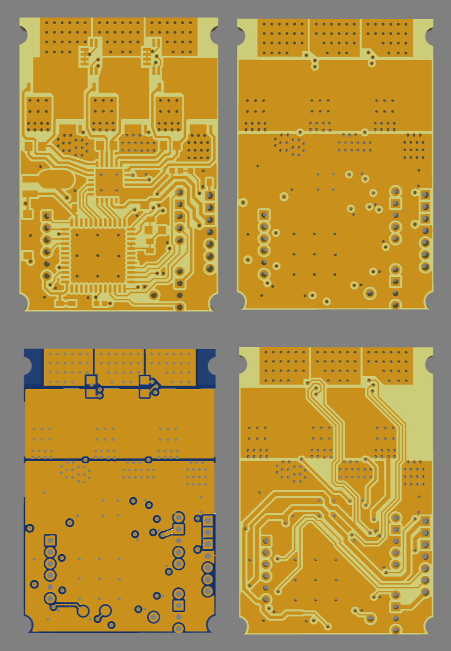
- Increased the board width by 1mm on the right to give the positive power rail more copper cross section, and removed an HV_IN trace on Inner2 which gives the ground rail another 25% or so copper cross section. The left-side power rails are now unnecessary except in the case of mounting two boards face-to-face.
I really should have finished testing everything before making a new version, but missed my chance when LCSC got a few DRV8300 back in stock. Still couldn’t make up my mind what all capacitors to buy, and now it’s back to waiting. What still needs tested:
- Buck converters
- I2C and encoder pins (unlikely to have any problems)
- Maximum current without copper bars
- JMSL0302AU mosfets (unlikely to make any noticeable difference)
I did a few price checks for single-sided JLC assembly. 10pcs dual-motor is under $8 per motor, 30pcs quad-motor under $5 per motor. Small quantities of single-motor are the most expensive. 5pcs is $12.80 without bucks, $13.80 with HV buck, and $15.80 with both (but low-voltage buck is generally not needed for single motor anymore, thanks to the larger 3V regulator). 10pcs with HV buck is $10 per motor.