Hi everyone,
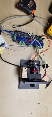
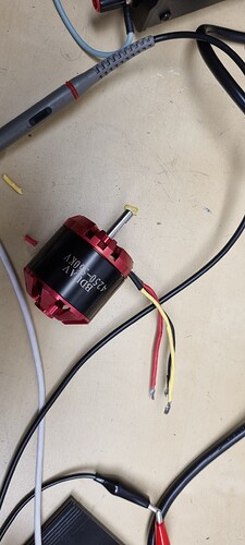
I’m starting to use SimpleFOC together with an ODrive board with a BLDC motor and an optical encoder.
Note that I’m brand new with SimpleFOC (but pretty experienced in programming, including all kind of microcontroller boards).
I got the code skeleton from the examples and this forum.
I checked the encoder standalone, which works fine. Then I checked the driver standalone, which works fine.
So far, so good.
Then I started with the very simple velocity_openloop mode, which works also fine: the motor rotate in the right direction, with the appropriate speed.
But I don’t succeed to do anything else. The velocity control (ie not openloop) does not work at all.
I tried to calibrate the PID’s as explained in this forum, without any success.
I digged a bit using the great simpleFOC-GUI, but no luck.
Any advice ?
My code :
#include <Arduino.h>
#include <SimpleFOC.h>
#include <SimpleFOCDrivers.h>
// https://github.com/simplefoc/Arduino-FOC/blob/master/examples/hardware_specific_examples/Odrive_examples/odrive_example_spi/odrive_example_spi.ino
// Odrive M0 motor pinout
#define M0_INH_A PA8
#define M0_INH_B PA9
#define M0_INH_C PA10
#define M0_INL_A PB13
#define M0_INL_B PB14
#define M0_INL_C PB15
// M0 currents
#define M0_IB PC0
#define M0_IC PC1
// Odrive M0 encoder pinout
#define M0_ENC_A PB4
#define M0_ENC_B PB5
#define M0_ENC_Z PC9
// M1 & M2 common enable pin
#define EN_GATE PB12
// SPI pinout
#define SPI3_SCL PC10
#define SPI3_MISO PC11
#define SPI3_MOSO PC12
Encoder encoder = Encoder(M0_ENC_A, M0_ENC_B, 5120, M0_ENC_Z);
/**
BLDCMotor class constructor
@param pp pole pairs number
@param R motor phase resistance - [Ohm]
@param KV motor KV rating (1/K_bemf) - rpm/V
@param L motor phase inductance - [H]
BLDCMotor(int pp, float R = NOT_SET, float KV = NOT_SET, float L = NOT_SET);
*/
BLDCMotor motor = BLDCMotor(14, NOT_SET , 600., NOT_SET);
// BLDCMotor motor = BLDCMotor(14);
BLDCDriver6PWM driver = BLDCDriver6PWM(M0_INH_A, M0_INL_A, M0_INH_B, M0_INL_B, M0_INH_C, M0_INL_C, EN_GATE);
// MagneticSensorSPI sensor = MagneticSensorSPI(AS5147_SPI, M0_ENC_A);
// low side current sensing define
// 0.0005 Ohm resistor
// gain of 10x
// current sensing on B and C phases, phase A not connected
LowsideCurrentSense current_sense = LowsideCurrentSense(0.0005f, 10.0f, _NC, M0_IB, M0_IC);
Commander command = Commander(Serial);
void doMotor(char *cmd) { command.motor(&motor, cmd); }
void doA()
{
encoder.handleA();
}
void doB()
{
encoder.handleB();
}
void doIndex()
{
encoder.handleIndex();
}
/*
0 : sensor only
1 : driver only
*/
unsigned char what = -1;
void setup_sensor_only()
{
encoder.quadrature = Quadrature::ON;
encoder.pullup = Pullup::USE_INTERN;
encoder.init();
encoder.enableInterrupts(doA, doB, doIndex);
Serial.println("Encoder ready");
}
void setup_driver_only()
{
bool ret;
driver.pwm_frequency = 20000;
driver.voltage_power_supply = 15;
driver.voltage_limit = 15;
ret = driver.init();
driver.enable();
Serial.println("Driver ready");
}
void setup()
{
bool ret;
Serial.begin(115200);
if (what == 0)
{
setup_sensor_only();
return;
}
if (what == 1)
{
setup_driver_only();
return;
}
driver.pwm_frequency = 20000;
// power supply voltage [V]
driver.voltage_power_supply = 15;
// Max DC voltage allowed - default voltage_power_supply
driver.voltage_limit = 12;
// driver init
ret = driver.init();
// link the motor and the driver
motor.linkDriver(&driver);
encoder.quadrature = Quadrature::ON;
encoder.pullup = Pullup::USE_INTERN;
encoder.init();
encoder.enableInterrupts(doA, doB, doIndex);
motor.linkSensor(&encoder);
// control loop type and torque mode
motor.torque_controller = TorqueControlType::voltage;
// resistance : 0.068 ohm
// motor.voltage_limit = motor.phase_resistance*motor.current_limit
// here : voltage_limit = 0.068 * current_limit(=.1)
//
motor.controller = MotionControlType::velocity_openloop;
// controller configuration based on the control type
// velocity PID controller parameters
// default P=0.5 I = 10 D =0
motor.PID_velocity.P = .05;
motor.PID_velocity.I = 1.;
motor.PID_velocity.D = 0.;
motor.LPF_velocity.Tf = 0.01;
// jerk control using voltage voltage ramp
// default value is 300 volts per sec ~ 0.3V per millisecond
motor.PID_velocity.output_ramp = 300;
// velocity low pass filtering
// default 5ms - try different values to see what is the best.
// the lower the less filtered
motor.LPF_velocity.Tf = 0.01;
// since the phase resistance is provided we set the current limit not voltage
// default 0.2
// motor.current_limit = 0.1; // Amps
// max voltage allowed for motion control
motor.voltage_limit = .6;
// alignment voltage limit
motor.voltage_sensor_align = 0.5;
// link the driver
current_sense.linkDriver(&driver);
// init the current sense
current_sense.init();
current_sense.skip_align = true;
motor.linkCurrentSense(¤t_sense);
command.add('M', doMotor, (char *)"motor");
// tell the motor to use the monitoring
motor.useMonitoring(Serial);
motor.monitor_downsample = 0; // disable monitor at first - optional
motor.init();
motor.initFOC();
delay(1000);
next_millis = HAL_GetTick() + 1000;
motor.move(.5);
}
void loop_sensor_only()
{
encoder.update();
float angle = encoder.getAngle();
float velocity = encoder.getVelocity();
long pulse = encoder.getPulse();
// display the angle and the angular velocity to the terminal
Serial.print("A:");
Serial.print(angle);
Serial.print("\t");
Serial.print("P:");
Serial.print(pulse);
Serial.print("\t");
Serial.println(velocity);
}
void loop_driver_only()
{
// setting pwm (A: 3V, B: 1V, C: 5V)
driver.setPwm(3, 1, 5);
}
void loop()
{
// Read the measured angle
// float angle = as5047p.readAngle();
if (what == 0)
{
loop_sensor_only();
return;
}
if (what == 1)
{
loop_driver_only();
return;
}
// encoder.update();
// foc loop
motor.loopFOC();
// motion control
motor.move();
// monitoring
motor.monitor();
// real-time commander calls
command.run();
/*
my_angle = encoder.getSensorAngle();
uint32_t now = HAL_GetTick();
if (next_millis && (now >= next_millis))
{
next_millis = now + 1000;
}
*/
}

