Runger;
the motor specs are here: motor stuff
The sensor, I think most have problems with it because the wrong magnets are often shipped. Happened to me but since fixing that I seem to get solid, repeatable results from mine and yes, using I2C.
Good news! I had some success! I loaded the “full_control_serial” example. Made minor tweeks to match the ESP32 and loaded it. It took a bit to find and use the correct commands but I was able to get my motor to actually move in an expected manor. Next I added the motor.monitor() function call and went to FOC Studio. I still have no values in the “FOC digital read out” but from the Cmd line window in Studio I as able to send commands much the same as the IDE serial monitor. On the “Device” window the graph now works and shows valid data. Changing the velocity PID P gain also worked and the motor behavior changed. This is a big step forward for me. I can now play with the tuning and see if I can set something up for this motor/sensor that works well.
Here is current code:
/**
 * Comprehensive BLDC motor control example using magnetic sensor
 *
 * Using serial terminal user can send motor commands and configure the motor and FOC in real-time:
 * - configure PID controller constants
 * - change motion control loops
 * - monitor motor variabels
 * - set target values
 * - check all the configuration values
 *
 * See more info in docs.simplefoc.com/commander_interface
 */
#include <SimpleFOC.h>

MagneticSensorI2C sensor = MagneticSensorI2C(AS5600_I2C);
BLDCMotor motor = BLDCMotor(11);
BLDCDriver3PWM driver = BLDCDriver3PWM(16,17,18,19);
Commander command = Commander(Serial);
void onMotor(char* cmd){ command.motor(&motor, cmd); }

void setup() {
  sensor.init();
  motor.linkSensor(&sensor);
  driver.voltage_power_supply = 14.8;
  driver.init();
  motor.linkDriver(&driver);
  motor.foc_modulation = FOCModulationType::SpaceVectorPWM;
  motor.controller = MotionControlType::torque;
  motor.PID_velocity.P = 0.2f;
  motor.PID_velocity.I = 20;
  motor.PID_velocity.D = 0;
  motor.voltage_limit = 12;
  motor.LPF_velocity.Tf = 0.01f;
  motor.P_angle.P = 20;
  motor.velocity_limit = 50;
  Serial.begin(115200);
  motor.useMonitoring(Serial);
  motor.init();
  motor.initFOC();
  motor.target = 2;
  command.add('A', onMotor, "motor");
  // Run user commands to configure and the motor (find the full command list in docs.simplefoc.com)
  Serial.println(F("Motor commands sketch | Initial motion control > torque/voltage : target 2V."));

  _delay(1000);
}


void loop() {
  motor.loopFOC();
  motor.move();
  motor.monitor();
  command.run();
}
I really don’t know yet how this code seems to work but the code from a few posts back did not.
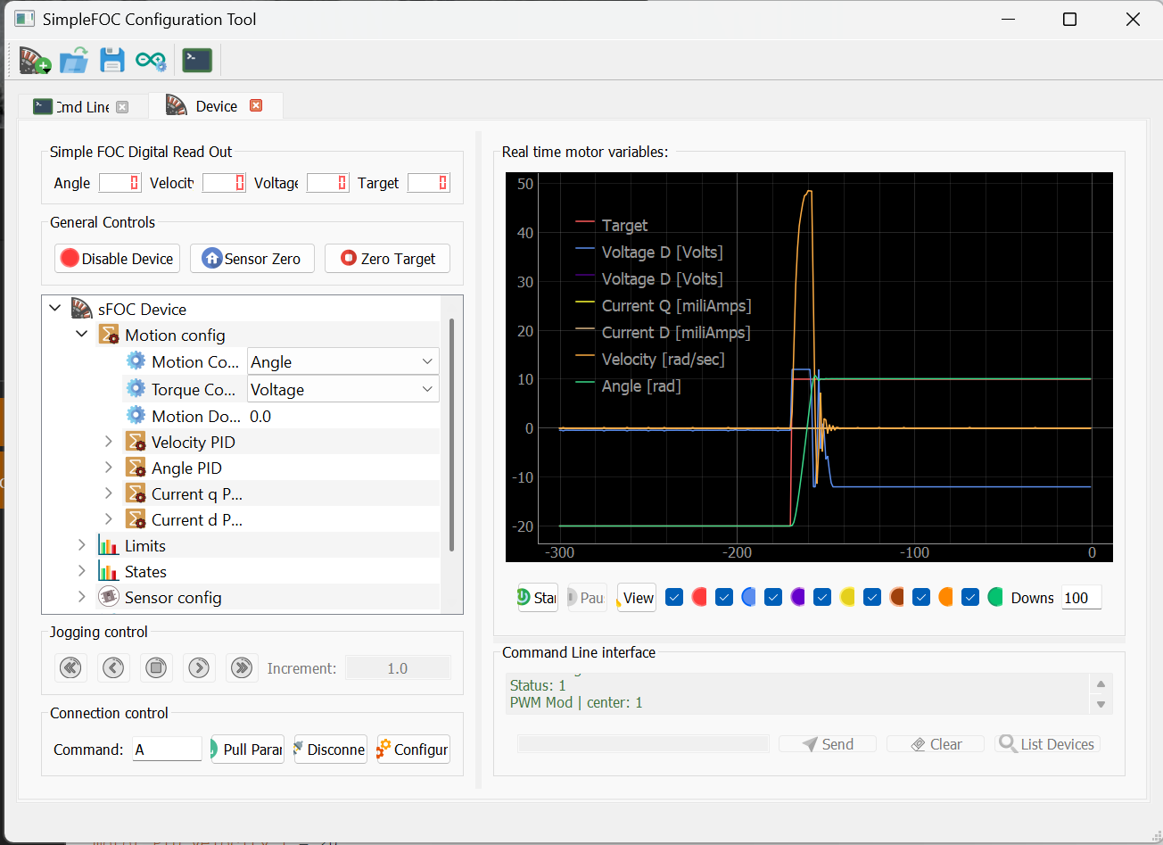
This is the graph of issuing an A10 command in Angle mode:
Hey, amazing, it looks like its working for you now!
I use these EMax motors a lot, they’re among my favourites as they perform well but aren’t too expensive.
Due to their high ohms and low KV they’re really easy to work with and tune. So I think you’ll get it all tuned and configured now that the setup is working for you!
No, they build on each other. So torque-voltage is closed loop but uses only the sensor. Velocity mode builds on this and adds the velocity PID. Angle mode uses the velocity PID and adds the angle P controller.
And finally torque-current modes add the current PID controllers as well.
You may find the modes work optimally with different tunings, but in principle you can tune them one by one and re-use the previous results as the starting point of the next more complex mode.
This indicates that the motor’s zero angle is not being found well. The PI values for velocity look a little high.
Is the motor under load during alignment? Is there a physical reason it isn’t finding the zero?
Is the voltage set high enough during alignment? With the emax motor you don’t need to be over-careful, its phase resistance is very high so currents won’t rise too high. This motor should align properly at a voltage of 5-10V with no load attached to it.
Is the pole count set correctly? This motor has 11 pole pairs IIRC.
If you can’t solve it with the above hints then it may be a problem of the sensor precision. You’re using the I2C mode of the AS5600, right?
The zero point on my motor/sensor stays consistent but is sensitive due to the resolution of the encoder. The motor is attached to the reaction wheel of the inverted pendulum and the pole count is set to 11. I also ran the pole count finder and it reports same.
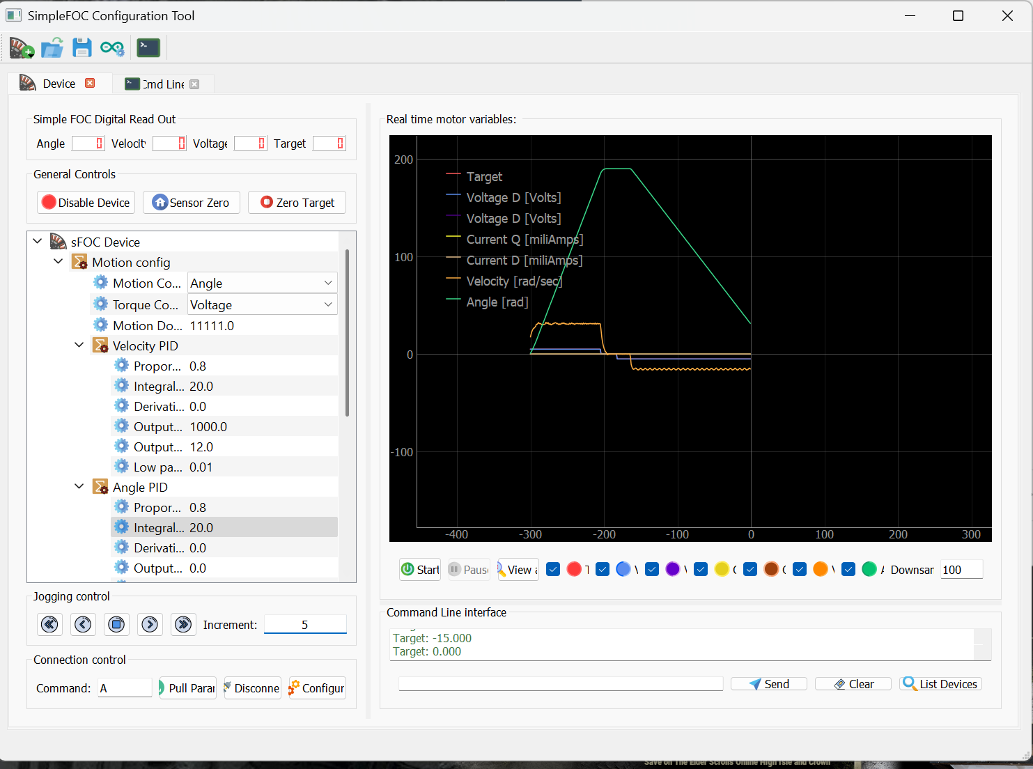
I did more experiments and adjustments and have the system working fairly smooth (most of the time!) Sometimes in a simple mode like open loop voltage, the motor will growl, it sounds very “notchy” other times with nothing changed…it runs silky smooth and quite. The only command I was giving it was A5…A-5…A0…A10 and such. I don’t know why. I found this motor likes about 8v. 10-12 and it over heats quick. I also reduced the angle P to .8 instead of 20. At 20 in the angle mode it would rotate to the target and oscillate. P at .8 and the oscillations would damp out.
I thought I would try and transfer my settings to the pendulum script and try it. I took out all the serial reporting in order to speed the loop and I think the result is now too quick. The reaction wheel oscillates at the bottom, moving back and forth about .5 rads pretty quickly. Estimate about thee times per second…to fast for it to begin to swing. Any suggestions?
#include <SimpleFOC.h>

#define sign(x) ((x) < 0 ? -1 : ((x) > 0 ? 1 : 0))
MagneticSensorI2C sensor = MagneticSensorI2C(AS5600_I2C);
MagneticSensorI2C pendulum = MagneticSensorI2C(AS5600_I2C);

// BLDC motor init
BLDCMotor motor = BLDCMotor(11);
// define BLDC driver
BLDCDriver3PWM driver = BLDCDriver3PWM(16,17,18,19);

// include commander interface
//Commander command = Commander(Serial);
//void doMotor(char* cmd) { command.motor(&motor, cmd); }

void setup() {
  sensor.init();
  motor.linkSensor(&sensor);
  motor.linkDriver(&driver);
  driver.voltage_power_supply = 14.8;
  driver.init();
  Wire1.begin(33, 32, (uint32_t)400000); //Keshka put sda on pin 33 and scl on 32 for second sensor
  pendulum.init(&Wire1);
  motor.torque_controller = TorqueControlType::voltage;
  motor.controller = MotionControlType::angle;
  motor.foc_modulation = FOCModulationType::SpaceVectorPWM;
  motor.PID_velocity.P = 0.2f;
  motor.PID_velocity.I = 20;
  motor.PID_velocity.D = 0;

  motor.voltage_limit = 8;
  motor.LPF_velocity.Tf = 0.01f;
  motor.P_angle.P = .8;
  motor.velocity_limit = 20;
  motor.init();
  motor.initFOC();
}

// loop down-sampling counter
long loop_count = 0;

void loop() {
  // ~1ms
  motor.loopFOC();

  // pendulum sensor read
  pendulum.update();

  // control loop each ~25ms
  if(loop_count++ > 25){

    // calculate the pendulum angle
    float pendulum_angle = constrainAngle(pendulum.getAngle() + _PI);

    float target_voltage;
    if( abs(pendulum_angle) < 0.5 ) // if angle small enough stabilize
      target_voltage = controllerLQR(pendulum_angle, pendulum.getVelocity(), motor.shaft_velocity);
    else // else do swing-up
      // sets 40% of the maximal voltage to the motor in order to swing up
      target_voltage = -_sign(pendulum.getVelocity())*driver.voltage_power_supply*0.4;

    // set the target voltage to the motor
    motor.move(target_voltage);

    // restart the counter
    loop_count=0;
  }
}

// function constraining the angle in between -pi and pi, in degrees -180 and 180
float constrainAngle(float x){
    x = fmod(x + _PI, _2PI);
    if (x < 0)
        x += _2PI;
    return x - _PI;
}

// LQR stabilization controller functions
// calculating the voltage that needs to be set to the motor in order to stabilize the pendulum
float controllerLQR(float p_angle, float p_vel, float m_vel){
  float u =  40*p_angle + 7*p_vel + 0.3*m_vel;
  if(abs(u) > driver.voltage_power_supply*0.7) u = sign(u)*driver.voltage_power_supply*0.7;
  return u;
}```
Just ran the KV estimator…it’s average is about 54 (motor claims 42). Would this help/hurt if I added
BLDCMotor motor = BLDCMotor(11,10.9,54);
rather than
BLDCMotor motor = BLDCMotor(11);
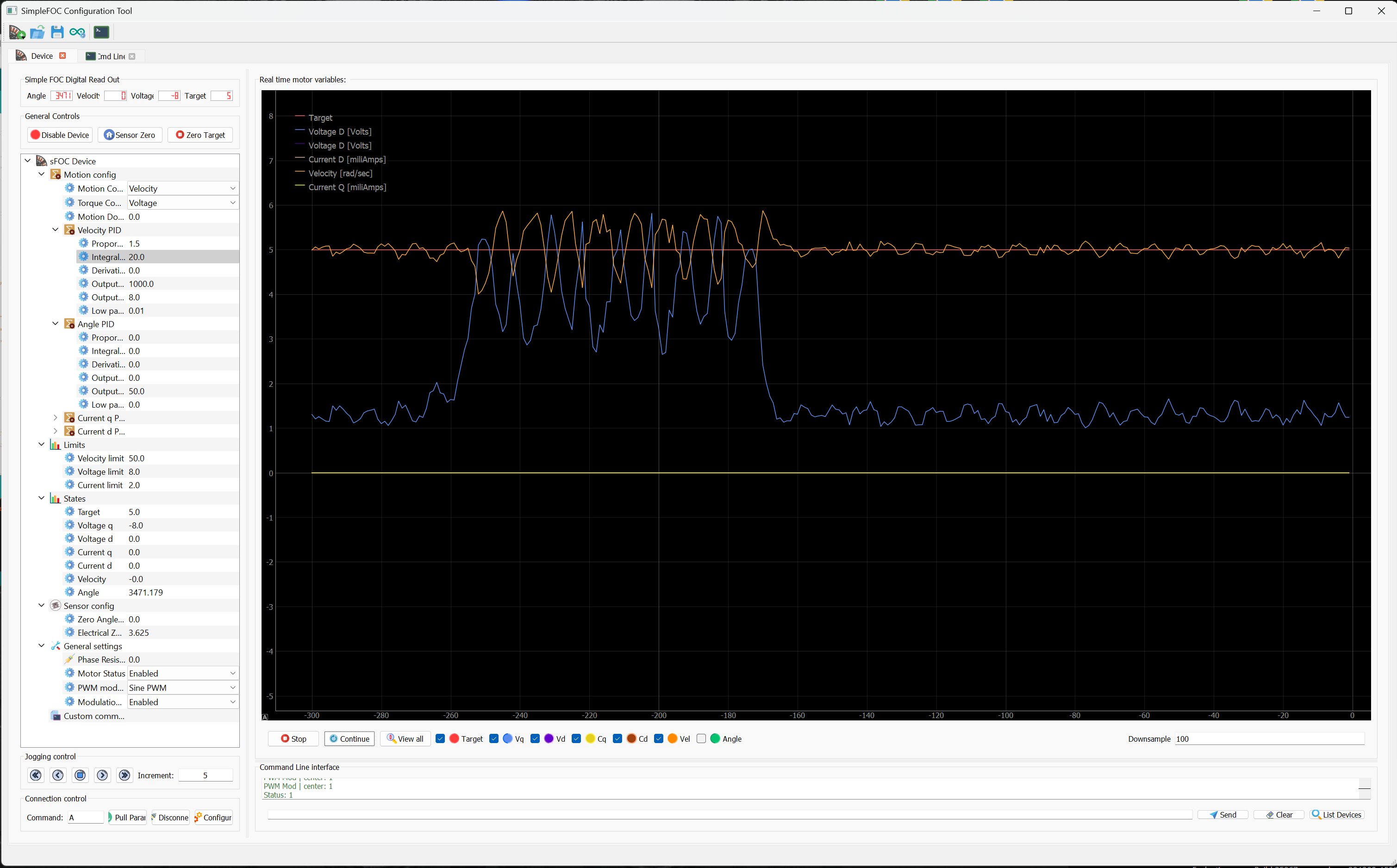
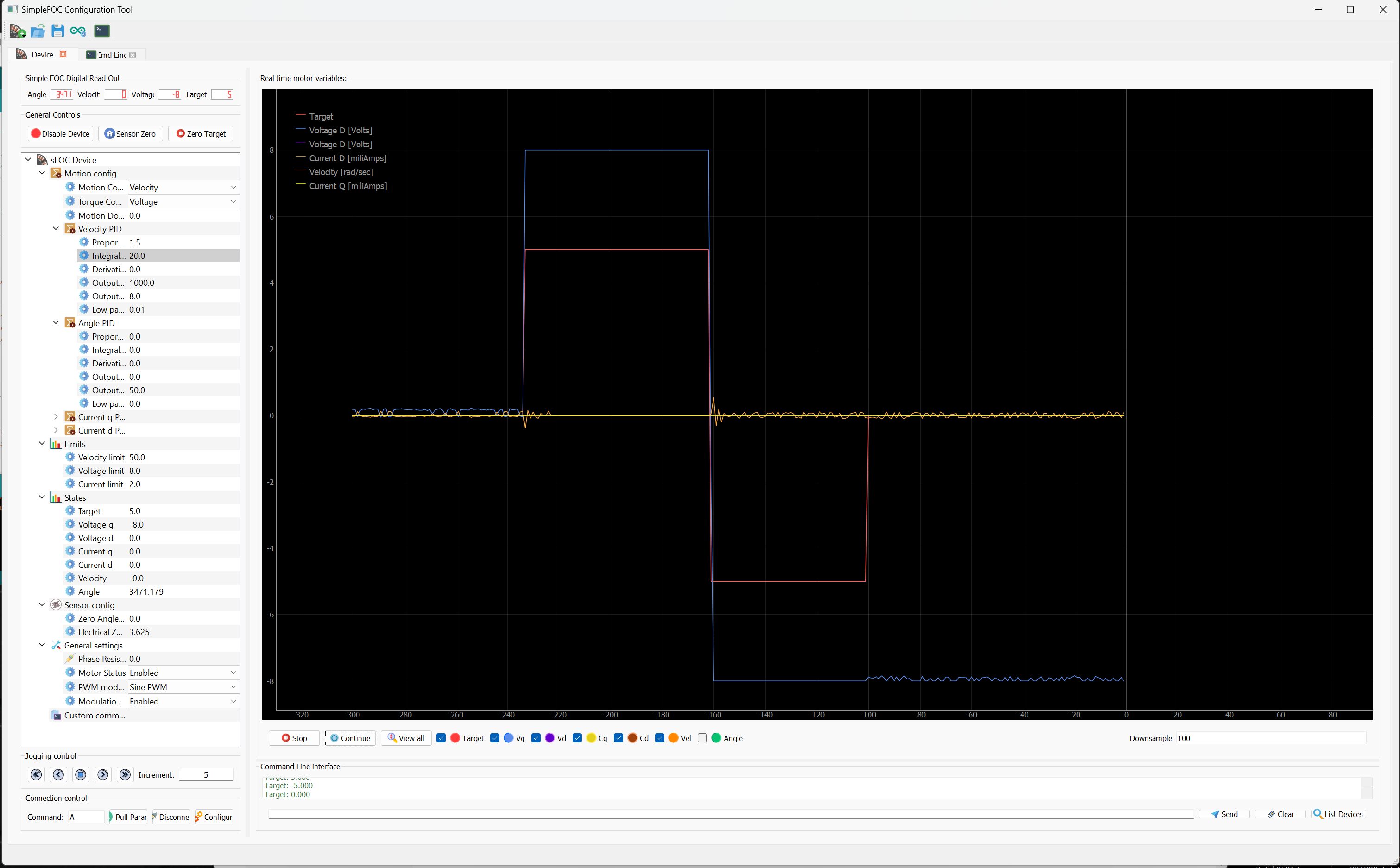
Playing with votage PID. Here is a capture of the motor turning at 5. Then a slight load put on the motor, then back to unloaded. Motor must still be hand started if stationary. It WILL reverse directions if already moving.
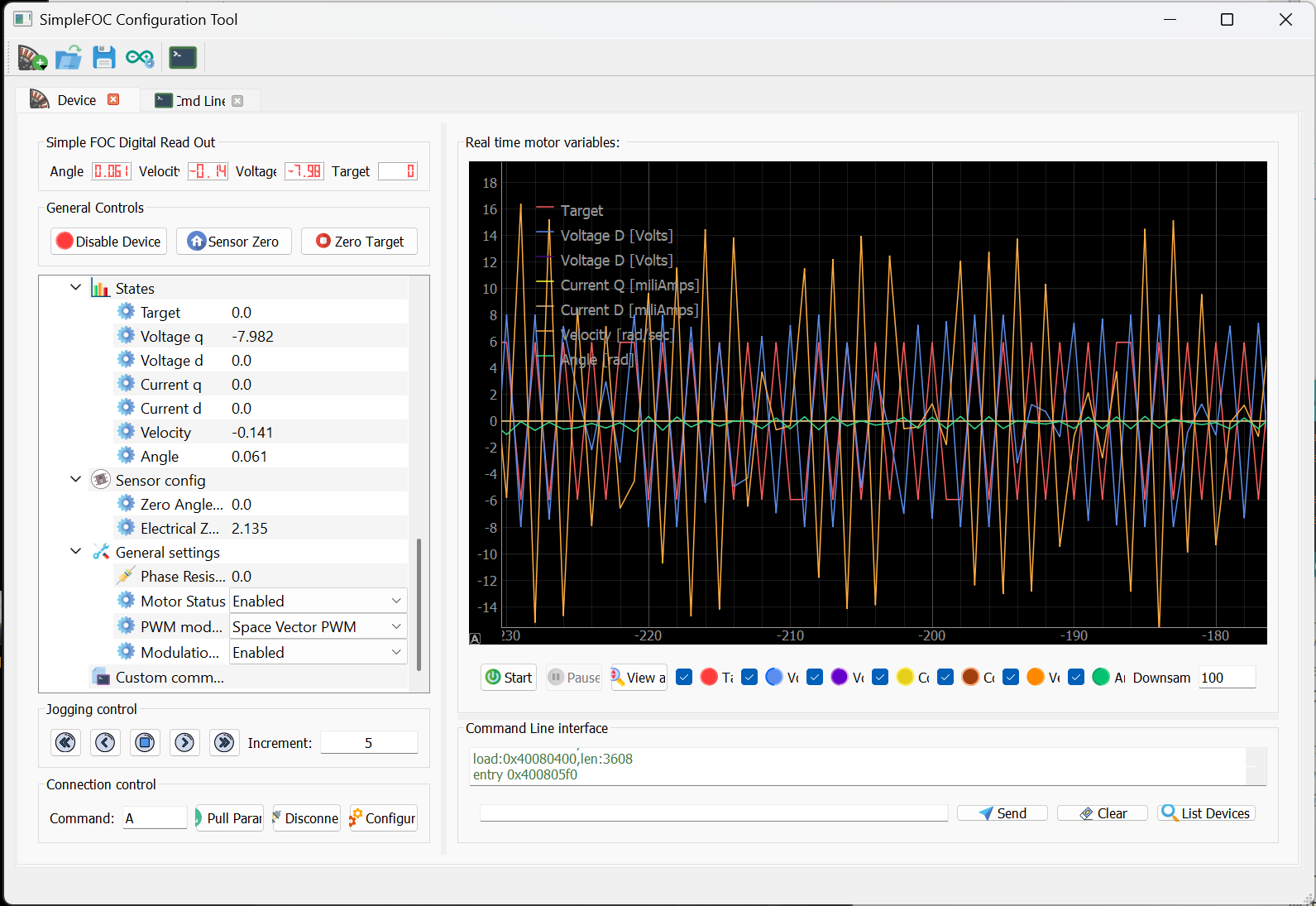
Here is the motor stationary…given +5 then -5 the 0. It shows a voltage is applied but no movement. Note that even after giving 0 (stop) the applied voltage remains.
No it is not used. Its just an informational check for your convenience and security
It always uses the value you set, no matter what happens in the PP check.
I’m very puzzled. Is it possible one of the phases is not working? Either not connected right, shorted, burn out or something? When only 2 of the three phases are working you can get some strange behaviour, and the motor can still be turning in some situations…
You nailed it Runger! The phase check was good on the motor and all three phases were withing 0.1ohm of each other but just for a test, I swapped it with the second motor I have. I noticed the problem motor seem much more notchy when rotated by hand while it had nothing connected to it compared to the second motor.
Upon mounting and testing the second motor, all tests work fine (yay!). It will start/stop in any mode, any direction and runs smooth. Tests done with the reaction wheel attached.
I don’t know what is wrong with the first motor other than one time while parked, I did not realize FOC had holding power passing through it and it got hot to the touch…hot enough to cause the 3D printed parts to sag. I know rare earth magnets hate that so I may have been damaged then. Other than that, it may have been bad from day one. Seems impossible to make such a nice motor for $8.50. Perhaps they are not tested when made.
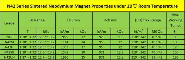
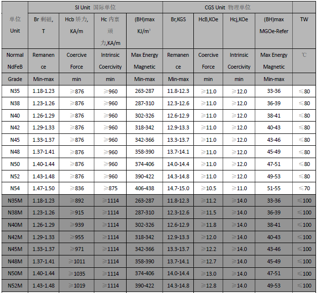
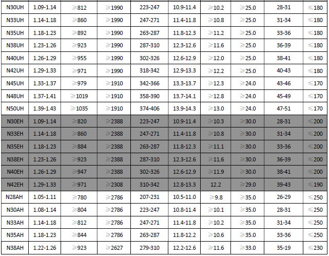
Rare earth magnets used in common BLDC permanently demagnetize at about 80oC which is less than the temperature of your morning coffee cup. There are magnets which may withstand higher temperatures however they are extremely expensive and I doubt you could buy them with these cheap Chinese motors.
If you melted the enclosure, then you definitely went way above 100oC and cooked your motor.