Getting closer - Shield setup!

Hi Runger;
sorry for the delay. I finished printing all the parts for the reaction wheel and had to wait for eBay to ship bearings. It’s all assembled on my desk now and I am starting the wiring and software. I used “magnetic_sensor_12c_example” to test the AS5600 and it shows stable readings for both pos and rate on the motor sensor. I am using an Arduino Mega2560 to test with and hope it performs well enough for the reaction wheel.

I see in your examples you have two sets of code under “magnetic_sensor_i2c_dual_bus_examples”. One for “esp32” and one for “stm32”. I am not real familiar with those terms. An internet search implies two different processor architectures and it doesn’t look like either apply to the Atmel2560. Do you have a sample for Arduino? I am trying to use a pair of AS5600 sensors for this project.

The code in “magnetic_sensor_12c_example” uses “sensor.init()” to start things with the AS5600 on the standard I2c bus for the Mega. To solve the problem of the AS5600 having a fixed address I could use something like this soft wire library “https://github.com/Seeed-Studio/Arduino_Software_I2C” but not sure how to attach it to sensor.init and sensor.getAngle and Velocity

The mega2560 is an 8bit 16MHz mcu, similar to Arduino uno with more pins and ram.

You are right about esp and stm32 being alternate architectures. They are 32bit and typically run at 70-240Mhz. Esp32 is dual core.

You have a bunch of factors working against you. Slow mcu, noisy magnetic sensor and dual motor. You should be able to get one motor tuned but will struggle with the second as the atmega is, imho, not fast enough.

And things get slower if you are using a software i2c as a second bus. This is sometimes called bit banging and is less efficient (more mcu cycles). An alternative would be to find a board that has 2nd icu bus or use i2c multiplexer.

Can you take a picture of your mega/driver/motor setup? I’d like to see if you could swap out the atmega for a nucleo or discovery board from ST. I realise that would be a whole new learning curve!

Happy to help see how far you can get with a mega. You’ve probably already seen that the init() method can take an optional TwoWire arg. If that software i2c implements the same interface, it is possible you could pass that on to your second sensor.

I agree with Owen.

I started out using the “SimpleBCG” board, which is a dual BLDC-driver with built-in ATMega328P - like the Arduino Nano. And it was quite easy to set up and program, and in the end I did get 2 motors spinning from I2C sensors.
But I had to modify SimpleFOC’s sensor code to reduce the number of sensor reads (because I2C is slow), and I have the feeling the whole setup is pushing the limits of the ATMega.

My next attempts were with ESP32 and STM32 - both of which are super-powerful, and have enough processing power to drive two motors. Adafruit has some very nice, easy-to-use and set up boards in the “Feather” format for both ESP32 and STM32. And the Nucleo Boards that Owen mentions are also very powerful, some come with Arduino headers and cost less than 20 EUR.
I think ESP32 is maybe a little bit easier to use than STM32, but both can be programmed from the Arduino environment.

I hope that soon we will also be able to recommend SAMD21-based MCUs, like the Arduino MKR1010 WiFi, or the Arduino Nano 33 IoT. I have been working on support for these in my dev branch of the code, and it is looking quite good.

Even if you use a faster MCU, you’ll still have the problem of reading two sensors quickly enough to drive the FOC algorithm for two motors. Software I2C would work, I think, but I think this is not the way to go. The MCUs like STM32 or ESP32 all have 2 or more I2C ports, so you could use 2 different I2C ports to make the AS5600 work for you.
Or you could use another sensor, like the AS5048B, which has I2C but with settable addresses. So then you can run two separate sensors on one I2C bus.

is this the right “thing” for an esp32 board?

It can be programmed with the Arduino ISP?

“C” code …Yes am pretty good at this. C++ …not so much, assembly code, not for decades!

Keshka

had a bit of a stupid moment and set back. Connected the AS5600 to 5v instead of 3.3v. They got hot and produce garbage for output now…three more ordered.

Owen, you comment that magnetic encoders are “noisy” . Earlier tests I made before “cooking” them seemed pretty stable. What is your experience? There is quite a price jump from ~$4 to ~$15 for a AS5048 and then ~$25 for the AMT103-V encoder.

Careful! I think this link is for the cable only. ESP32 boards are cheap, but $0.86 is a little too cheap. I think this is a misleading offer. In general, I would not prefer eBay for buying electronics if possible. Banggood, AliExpress or of course Mouser/Digikey are better sources, although admittedly sometimes eBay has things no one else does.
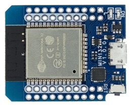
But for ESP32, I would go for something like this Wemos ESP32 module:
image
It is very small, but has 40 pins…

Yes, ESP32 can be programmed with Arduino IDE. I have good experiences doing this, it was quite easy to set up and get everything working. There are examples for using SimpleFOC with ESP32 in the code.

If you need the UNO form-factor, maybe something like this one?
Haven’t tried this myself though, so I don’t know how well supported it will be in terms of the board definitions.

You program it via a Micro USB cable, directly from Arduino IDE.
Once you have flashed your program once, you can include OTA (over the air) update functionality, since the ESP32 has WiFi… this is the nicest way to program, super-fast and no messing with the buttons or USB cables.

I just wanted to confirm that D1 R32 ESP32 boards with Arduino header work well with the library. Especially in combination with SimpleFOCShields, they have a good performance with current sensing as well.

The only real problem I encountered is due to the nonlinear ADC characteristic. But that seems to be the issue of the esp32 in general and not just these boards. Otherwise I recommend them!

My point about noisy sensor is specific to AS5600. It claims 12 bit precision of angular precision but the last 2 bits jump around which is picked up by SimpleFOC as rapid movement and requires Tf smoothing to compensate.

Other sensors are 14 bit e.g as5048, don’t fluctuate as much and tuning is easier.

Does the esp32 have enough pins for dual?
I suspect it should be ok but will need careful thought. 6pwm pins + 4 i2c + current sense pins (if required) If you go by the numbers, it has enough pins but some are reserved for sd, some are analog, etc.

I agree that esp32 is a relatively easy next step from arduino uno. Stm is harder because there are so many variants!

I can confirm it does… but of course it depends on the exact board you choose on whether those pins are accessible… for example, don’t pick the ESP32-Cam based boards for motor control. Too few pins.

But the Wemos ESP32 module I mentioned above exposes 40 pins, most of which are some kind of IO. And the io-mux of the ESP32 can assign most peripherals to most pins, so you don’t have the same kind of restrictions on pin-assignment you do with the SAMD and STM32 cores, where each peripheral (e.g. a timer) is only assignable to a few pins.

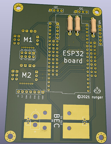
Here’s a schematic for a carrier board I had made, which connects either the Wemos Module or a DevKitC module to 2x 3-PWM driver:


The ESP32 Wemos Board has plenty of pins left over even with 2 motor drivers, SPI, I2C and 3 pins for monitoring outputs. I think 6-pwm could work too. Coupled with a full-featured driver like many of the TI chips I think it is a great MCU for hobbyist motor control.

Is it the right chip for a hardcore 6-pwm current sensing driver? I’m not sure. As Antun pointed out, the ADC is bad. Everyone says so, and while you can do things to calibrate it and improve it, the other architectures seem to have better ADCs. On the other hand, all the built-in features (like WiFi) can make for a highly integrated solution where other MCUs need supporting chips to do the same things. But I am sure @David_Gonzalez could say more about that, since he’s been using it in his Dagor controller…

A post was split to a new topic: Can someone show examples of the commands you can type in to do different things?

Hi gang! I have some time to get back to this project. I purchased a ESP32 WROOM-32 Wemos D1 LOLIN32 WIFI+BT 2.4GHz Dual Mode Developer Board. I have the Arduino IDE ver 1.8.13 and the ESP32 libraries installed and have uploaded some simple scripts such as blink and fade.

Next I tried the ESP32 position motion control example with magnetic sensor example and it creates compiler errors. Any ideas?
:

D:\Keshka\Documents\Arduino\libraries\Simple_FOC\src\drivers\hardware_specific\esp32_mcu.cpp: In function ‘void _configureTimerFrequency(long int, mcpwm_dev_t*, mcpwm_unit_t, float)’:
D:\Keshka\Documents\Arduino\libraries\Simple_FOC\src\drivers\hardware_specific\esp32_mcu.cpp:93:48: error: ‘MCPWM_SELECT_SYNC_INT0’ was not declared in this scope
mcpwm_sync_enable(mcpwm_unit, MCPWM_TIMER_0, MCPWM_SELECT_SYNC_INT0, 0);
^~~~~~~~~~~~~~~~~~~~~~
D:\Keshka\Documents\Arduino\libraries\Simple_FOC\src\drivers\hardware_specific\esp32_mcu.cpp:93:48: note: suggested alternative: ‘MCPWM_SELCT_SYNC0’
mcpwm_sync_enable(mcpwm_unit, MCPWM_TIMER_0, MCPWM_SELECT_SYNC_INT0, 0);
^~~~~~~~~~~~~~~~~~~~~~
MCPWM_SELCT_SYNC0
D:\Keshka\Documents\Arduino\libraries\Simple_FOC\src\drivers\hardware_specific\esp32_mcu.cpp:97:23: error: ‘volatile struct mcpwm_timer_regs_t’ has no member named ‘sync’
mcpwm_num->timer[0].sync.out_sel = 1;
^~~~
D:\Keshka\Documents\Arduino\libraries\Simple_FOC\src\drivers\hardware_specific\esp32_mcu.cpp:99:23: error: ‘volatile struct mcpwm_timer_regs_t’ has no member named ‘sync’
mcpwm_num->timer[0].sync.out_sel = 0;
^~~~
exit status 1
Error compiling for board ESP32 Dev Module.

1 Like

This seems like an old issue that we’ve had with the arduino esp32 package versions lower than 2.0.1

make sure to have esp32 package in your package manager higher than 2.1 The library officially does not support the old packages any more.

Thanks Antun, Arduino says this is what I have:

Huh, that’s interesting.
Do you have an old SimpleFOClibrary version then?

1 Like

2.0.0 was installed …updated to 2.2.3

that fixed it! Code uploaded to ESP32 WROOM-32 Wemos D1 LOLIN32 WIFI+BT 2.4GHz Dual Mode Developer Board

Thank you Antun

Many successes today. I began by testing my reaction wheel setup. Last time I played with it I had trouble getting logical results out of the AS5600’s. Testing today showed similar results. I apparently ordered new ones March of 21 so I got one of those out and tried it. It worked fine! Comparison between the old and new showed me the old had been shipped with the wrong magnets (they were not polarized correctly), replacing them and the old encoders now work fine and I was able to duplicate the results on the ESP32. Next tests were for motor control using the open loop velocity example. Putting in the values for my motors: BLDCMotor(11,10.9,42); and using a 4S lipoly battery at 14.8v. The motor would run up to a target velocity of 25. Past that and it would turn slower and shake. I had set the voltage limit to 6v. More than 6v did not seem to matter, less and the velocity would not go as high. Next I was able to get this test onto the ESP32 as well. Next I tried the Angle_Control_example. I had the motor of my reaction wheel connected for this test. I mostly worked but the motor suspended from the pendulum and having the reaction wheel on it, it would overshoot and begin oscillations. My guess is tuning will correct this and “how to” is the next subject of study. I am also going to try the reaction wheel script tomorrow morning but it’s late tonight and time for a break.

2 Likes

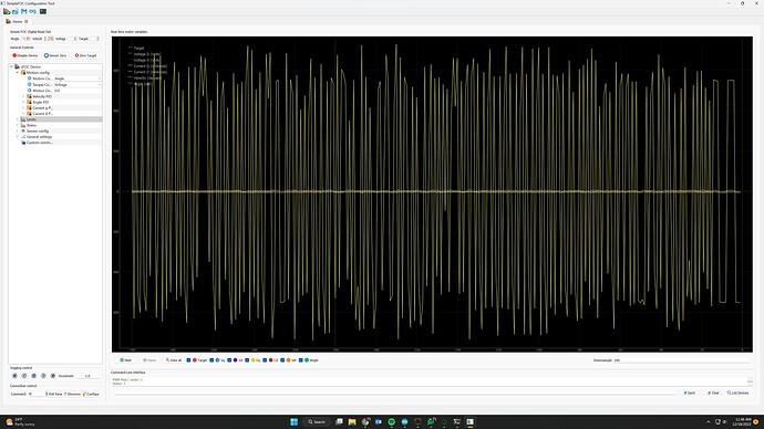
Been playing with it today. Ran the code, the reaction wheel jitters back and forth. sometimes it damps out and stops, other times I can add a bit of friction with my finger and stop it. I never tries to spin in such a way that might result in swinging the pendulum. I add the code and installed SimpleFOCStudio and below is a trace it made.

While the motor was stationary and I was reading…maybe an hour? I noticed what looked like a motor mounting screw might have backed out but no! The motor had gotten quite HOT and was melting the 3D printer material. I don’t think I “smoked” anything but wow.

attached is my current code, most from your examples and a photo of the Studio output. Since I get stable and predictable readings from both encoders - at this point I don’t think they are causing problems. I think it is a matter of tuning but I have no idea where or how to start. I see posts that suggest PID adjustments but is there no logical approach to this? Simply changing numbers at random does not seem productive.

I feel like I need to reload the position_motion_control script and do any tuning there. Seems that must work correctly before the pendulum program could.

Here is my code, it is running on an SP32 WROOM-32 Wemos D1 LOLIN32 WIFI+BT 2.4GHz Dual Mode Developer Board:

#include <SimpleFOC.h>

#define sign(x) ((x) < 0 ? -1 : ((x) > 0 ? 1 : 0))
MagneticSensorI2C sensor = MagneticSensorI2C(AS5600_I2C);
MagneticSensorI2C pendulum = MagneticSensorI2C(AS5600_I2C);

// BLDC motor init
BLDCMotor motor = BLDCMotor(11,10.9,42);
// define BLDC driver
BLDCDriver3PWM driver = BLDCDriver3PWM(16,17,18,19);

// include commander interface
Commander command = Commander(Serial);
void doMotor(char* cmd) { command.motor(&motor, cmd); }

void setup() {
  
  // initialize motor encoder hardware
  sensor.init();
  motor.linkSensor(&sensor);

  // driver config
  driver.voltage_power_supply = 14.8;
  driver.init();
  
  // init the pendulum encoder
    Wire1.begin(33, 32, (uint32_t)400000); //Keshka put sda on pin 33 and scl on 32 for second sensor
    pendulum.init(&Wire1);

  //PciManager.registerListener(&listenerPA);
  //PciManager.registerListener(&listenerPB);
  
  // set control loop type to be used
  motor.torque_controller = TorqueControlType::voltage;
  motor.controller = MotionControlType::torque;

  // link the motor to the encoder
  motor.linkSensor(&sensor);
  // link the motor to the driver
  motor.linkDriver(&driver);
  
  // initialize motor
  // driver config
  // power supply voltage [V]
  driver.voltage_power_supply = 14.8;
  driver.init();
  // link the motor and the driver
  motor.linkDriver(&driver);

  // choose FOC modulation (optional)
  motor.foc_modulation = FOCModulationType::SpaceVectorPWM;

  // set motion control loop to be used
  motor.controller = MotionControlType::angle;

  // contoller configuration
  // default parameters in defaults.h

  // velocity PI controller parameters
  motor.PID_velocity.P = 0.2f;
  motor.PID_velocity.I = 20;
  motor.PID_velocity.D = 0;
  // maximal voltage to be set to the motor
  motor.voltage_limit = 6;

  // velocity low pass filtering time constant
  // the lower the less filtered
  motor.LPF_velocity.Tf = 0.01f;

  // angle P controller
  motor.P_angle.P = 20;
  // maximal velocity of the position control
  motor.velocity_limit = 5; //was 20
  // use monitoring with serial
  Serial.begin(115200);
  // comment out if not needed
  motor.useMonitoring(Serial);


  // initialize motor
   motor.init();
  // align encoder and start FOC
  motor.initFOC();

  // add the motor to the commander interface
  // The letter (here 'M') you will provide to the SimpleFOCStudio
  command.add('M',doMotor,"motor");
  // tell the motor to use the monitoring
  motor.useMonitoring(Serial);
  motor.monitor_downsample = 0; // disable monitor at first - optional
  
}

// loop down-sampling counter
long loop_count = 0;

void loop() {
  // ~1ms 
  motor.loopFOC();

  // pendulum sensor read
  pendulum.update();

  // control loop each ~25ms
  if(loop_count++ > 25){
    
    // calculate the pendulum angle 
    float pendulum_angle = constrainAngle(pendulum.getAngle() + _PI);

    float target_voltage;
    if( abs(pendulum_angle) < 0.5 ) // if angle small enough stabilize
      target_voltage = controllerLQR(pendulum_angle, pendulum.getVelocity(), motor.shaft_velocity);
    else // else do swing-up
      // sets 40% of the maximal voltage to the motor in order to swing up
      target_voltage = -_sign(pendulum.getVelocity())*driver.voltage_power_supply*0.4;

    // set the target voltage to the motor
    motor.move(target_voltage);

    // restart the counter
    loop_count=0;
  }
     // real-time monitoring calls
  motor.monitor();
  // real-time commander calls
  command.run();

}

// function constraining the angle in between -pi and pi, in degrees -180 and 180
float constrainAngle(float x){
    x = fmod(x + _PI, _2PI);
    if (x < 0)
        x += _2PI;
    return x - _PI;
}

// LQR stabilization controller functions
// calculating the voltage that needs to be set to the motor in order to stabilize the pendulum
float controllerLQR(float p_angle, float p_vel, float m_vel){
  // if angle controllable
  // calculate the control law 
  // LQR controller u = k*x
  //  - k = [40, 7, 0.3]
  //  - x = [pendulum angle, pendulum velocity, motor velocity]' 
  float u =  40*p_angle + 7*p_vel + 0.3*m_vel;
  
  // limit the voltage set to the motor
  if(abs(u) > driver.voltage_power_supply*0.7) u = sign(u)*driver.voltage_power_supply*0.7;
  
  return u;
}

Here is the trace:
Hey @Keshka !

Did you get it running more smoothly?

Without tuning the PID it’s not surprising it doesn’t quite work yet…

Have you had a try at tuning it? Do you still need some pointers on doing the tuning?

Runger; Not yet, I am having some problems with FOCStudio I posted in a new thread. Part of my problems comes from not knowing what kind of behavior I should expect out of SimpleFOC with my motor/encoder setup. Example, I am hoping my setup will be able to accelerate to a target RPM then decelerate and stop at a repeatable position much like a servo motor will do. So far, this is not the case and I am having a hard time figuring out how to solve this. Best so far is motor spinning at around 15-20 rad/s if I help it (it will not self start) and motion is very weak. Even without the reaction wheel attached to the motor.

Yes, this is a reasonable expectation! I can tell you from experience that with a gimbal type motor you can easily achieve this. With a lower ohm, fast turning motor, it can be a bit more difficult to tune it, but it is still possible to achieve position control.

The MCU you’re using, an ESP32 is very fast and well suited to motor control. When using the ESP32 you have to program it quite carefully, to make sure the motor control tasks run quickly in a tight loop, with no delays. So using WiFi from within the same thread is generally not a good idea, for example.

I am not sure which motor you’re using… could you provide some details?

The sensor you’re using, the AS5600, is not a great sensor. Be sure to use the I2C mode, and not the PWM mode, but even in I2C mode it is very slow and inaccurate. So using this sensor is making your life a little harder, and will definately limit the speed you can achieve. But many users have successfully used the AS5600 (since the low price makes it attractive) so I am sure you can too!