I wanna make something similar to the dengFOC/dualFOC driver board, but much more compact, hopefully cheaper, and with an integrated g473 mcu. I’d probably use it to drive iPower 2804 or cubemars gl-30 motors. The board will mainly be used as a smart knob and to drive tendons in a robot hand. I may also use it as a generic BLDC motor driver for future projects. I plan to put a JST-SH footprint beside the magnetic encoder that breaks out the communication lines so that the motors may not necessarily be mounted together directly on the back of the PCB.
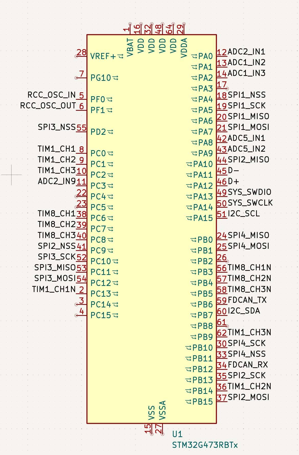
MCU: STM32G473
Gate driver: FD6288Q
CSA: TPA132A2 or INA240A2
Magnetic Encoder: MT6701
I was looking at fets and found some dual channel varieties: https://www.lcsc.com/product-detail/C53069588.html?s_z=n_XRS60J04F The RDSon is not bad, but will it complicate layout? It seems like most designs use two separate fets, is it for legacy, thermal, cost, and/or layout reasons?
Probably will use 10mOhm for current sensing and 2 100uF bulk caps per motor
Would appreciate some buck/ldo recommendations, as well as some pointers on where I need to put things like ESD/TVS diodes and snubbers. Was planning to use a REF3033AIDBZR for voltage reference, but haven’t put much thought into it.
Is this hardware overkill for a 2804? should I just slap two microsporas together and call it a day?Also would be interested in how big of a motor this stuff could drive, assuming I route it competently… as much of a learning experience as it will be a practical board, so advice about making my life easier would be appreciated. I recently fabbed @VIPQualityPost ‘s Lemon Pepper Stepper on my openPnP machine, but that should be a thread of it’s own.
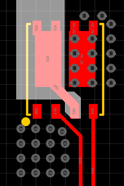
My first designs used a dual-channel mosfet called SE3082G, which originally had an internal connection between the drain of one and source of the other, making it very elegant for half-bridge use. But it was the only one of its kind, and was changed to be like all the others where you have to make the connection on the PCB, which either requires a thin trace squeezing between pins as shown below, or utilization of other layers which eliminates the ability to use the back of the board as two fat power rails like I normally do.
I switched to using two 3mm single-channel mosfets since they take up about the same total board space as one dual-channel 5x6mm, have lower RDSon, and have three source pins each instead of just one so there’s less of a pinch point. My
Gooser project is similar to your proposal, but with less accurate hall current sensors.
But I’d recommend going with smaller integrated drivers like DRV8316. Discrete mosfets are very much overkill for a 2804 gimbal. From my testing, cheap 40V rated can do about 8 amps continuous without cooling, expensive 30V can do 15 amps. And you can run twice that much current for a little while, and probably continuously with heatsink and fan. Meanwhile your motors will probably overheat at less than 1 amp.
Nice project!
The drv8316 is really nice and it makes perfect sense to use it for such project.
Microspora is a very good starting point. I love that board 
We have continued working on it a bit more after the initial release from @rambros.
Its now a 4 layer board and has a lot of JST connectors for easier use.
Here is the easyeda link: MicroSpora - SimpleFOC - Platform for creating and sharing projects - OSHWLab
One thing to consider with microspora is that its using the SPI version of the DRV8316R, in most cases you dont necessarily need all this DRV8316 configuration to be done on startup and the configuration stays always the same. Also for low power motors there is no real big point in using 6pwm. 2x 6pwm + 2x SPI will use a lot of pins and you might not have enough if you plan using the stm32g4 chip.
I’d suggest using the DRV8316T where you can do all the configuration in hardware with no SPI connection at all. There are some choices to be made but it can reduce the complexity of the board by a lot.
Here are a couple of project examples:
They all use the DRV8316T and QtFOC also uses onboard LDO.
Good luck!
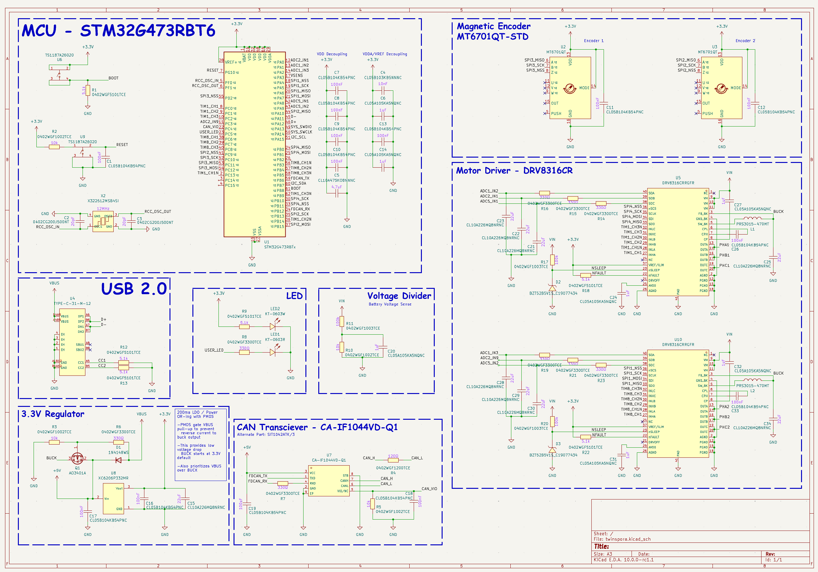
I asked some more questions on the SimpleFOC discord, and arrived to the same conclusion as @dekutree64 . Thanks to @runger for helping me answer a lot of them. Apparently I can use 3 ADCs to drive both motors, each ADC being connected to both motors. Going to be heavily inspired by @rambros ‘s microspora, maybe I’ll call it the twinspora? Will be using the DRV8316CR. The only difficulty seems to be that I can’t find any of the CAN Transciever (CA-IF1044) in stock anywhere, I’d prefer using it over the big SOIC-8 packages, but maybe I’ll end up using an SN65HVD230DR or a TCAN1044AEVDRQ1, since I already have some of those on hand……
Quickly threw together the schematic – again, credit to @rambros for majority of the design, I’ve only swapped the MCU and doubled up the motor driver + magnetic encoder.
Time to see what the routing is like in KiCad…..