Hello,
I hope you are doing well.
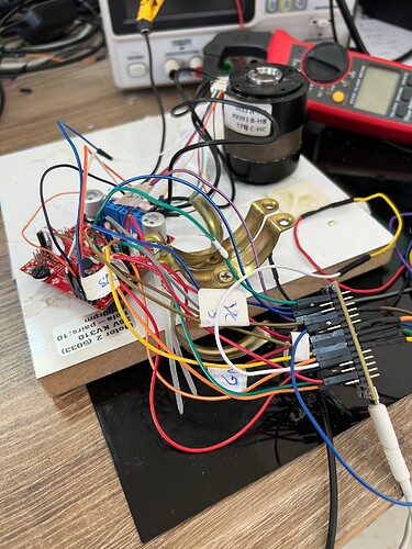
I work as an embedded systems engineer, focusing on developing software for client product firmware. Recently, I encountered a client project where one part involved developing software to control a three-phase BLDC motor equipped with integrated Hall sensors in the stator, powered by 24V and featuring 20 poles (10 pole pairs).
In this project, I developed an algorithm on an STM32G431KBT6 development board using the FOC (Field-Oriented Control) strategy. I implemented the algorithm with the SimpleFOC library in closed-loop mode to achieve velocity control, using space vector PWM and torque control through voltage modulation. If needed, I can provide further details about the code, which was developed in the Arduino IDE.
The results were promising in terms of speed, torque, and current consumption. According to the project’s requirements, the motor was expected to operate between 3000 RPM and 8000 RPM. While the motor performed well at all lower speeds, we observed that it could not exceed 6300 RPM, even though it should have reached the desired 8000 RPM.
Interestingly, when we tested the same motor with a simpler control strategy, such as servo control or a 1-PWM control mode, it reached 8000 RPM without any issues, which confirms that the motor is capable of achieving the target speed.
In terms of microcontroller performance, the STM32G431KBT6 is powerful enough to run the algorithm efficiently, given its high processing capability. I also double-checked the hardware connections, and everything appears to be properly connected.
As part of the debugging process, I tried adjusting parameters such as voltage_limit, voltage_power_supply, pwm_frequency, and output_ramp, but that did not solve the issue. The only modification that had an effect was increasing the voltage from 24V to 30V, which allowed the motor to reach 7000 RPM. However, this is not a viable solution, as the system is required to operate at 24V.
After further analysis, I suspect that the issue may be related to the internal behavior of the FOC method, particularly with the way vector variables are managed.
If you have any insights or suggestions on how to address this problem, or if you can provide guidance on the next steps to take, it would be greatly appreciated.
Thank you very much for your time and support. I am at your disposal if you need any additional information.
#include <SimpleFOC.h>
#include <SPI.h>
#include <stm32g4xx_hal.h>
#define   _MON_TARGET 0b1000000  // monitor target value
#define   _MON_VOLT_Q 0b0100000  // monitor voltage q value
#define   _MON_VOLT_D 0b0010000  // monitor voltage d value
#define   _MON_CURR_Q 0b0001000  // monitor current q value - if measured
#define   _MON_CURR_D 0b0000100  // monitor current d value - if measured
#define   _MON_VEL    0b0000010  // monitor velocity value
#define   _MON_ANGLE  0b0000001  // monitor angle value
ADC_HandleTypeDef hadc1;
ADC_HandleTypeDef hadc2;
I2C_HandleTypeDef hi2c1;
SPI_HandleTypeDef hspi1;
TIM_HandleTypeDef htim1;
TIM_HandleTypeDef htim2;
TIM_HandleTypeDef htim3;

UART_HandleTypeDef huart2;
//-----------------------------------------------------------------END SPI PART
//stm32 defines
/* Private defines -----------------------------------------------------------*/
#define ADC_NTCMotorTemp_Pin GPIO_PIN_0
#define ADC_NTCMotorTemp_GPIO_Port GPIOF
#define ADC_Voltage_Pin GPIO_PIN_1
#define ADC_Voltage_GPIO_Port GPIOF
#define NRST_Pin GPIO_PIN_10
#define NRST_GPIO_Port GPIOG
#define INHC_Pin GPIO_PIN_0
#define INHC_GPIO_Port GPIOA
#define ADC_Pressure_Pin GPIO_PIN_1
#define ADC_Pressure_GPIO_Port GPIOA
#define UART_TX_NRF52_Pin GPIO_PIN_2
#define UART_TX_NRF52_GPIO_Port GPIOA
#define UART_RX_NRF52_Pin GPIO_PIN_3
#define UART_RX_NRF52_GPIO_Port GPIOA
#define ADC_BoardTemp_Pin GPIO_PIN_0
#define ADC_BoardTemp_GPIO_Port GPIOB
#define INHA_Pin GPIO_PIN_8
#define INHA_GPIO_Port GPIOA
#define INLA_Pin GPIO_PIN_9
#define INLA_GPIO_Port GPIOA
#define HALLB_Pin GPIO_PIN_10
#define HALLB_GPIO_Port GPIOA
#define HALLA_Pin GPIO_PIN_11
#define HALLA_GPIO_Port GPIOA
#define HALLC_Pin GPIO_PIN_12
#define HALLC_GPIO_Port GPIOA
#define INLC_Pin GPIO_PIN_3
#define INLC_GPIO_Port GPIOB
#define INHB_Pin GPIO_PIN_4
#define INHB_GPIO_Port GPIOB
#define INLB_Pin GPIO_PIN_5
#define INLB_GPIO_Port GPIOB
#define ENABLE_Pin GPIO_PIN_6
#define ENABLE_GPIO_Port GPIOB
#define BOOT0_Pin GPIO_PIN_8
#define BOOT0_GPIO_Port GPIOB
#define HALLA PA11
#define HALLB PA10
#define HALLC PA12   //PA11 //NEW PB11
#define INHA  PA8    //TIM2 CH3 PA2  -----//new- //TIM1 CH1 PA8                          //pb6
#define INHB  PB4   //TIM4 CH1  PB6 //TIM1 CH4 PA11  ----- //new- //TIM1 CH2 PA9
#define INLA  PA9  //TIM2 CH4 PA3   //new- //TIM1 CH1N PA7                                 //PB7
#define INLB  PB5  //TIM4 CH2  PB7//TIM1 CH2 PA9   -----//new- //TIM1 CH2N  PB0
#define INHC  PA0  //TIM4 CH2  PB7//TIM1 CH2 PA9   -----//new- //TIM1 CH2N  PB0
#define INLC  PB3 //TIM4 CH4  PB9 //TIM1 CH1 PA8 ---- //new- //TIM1 CH3N PB1
#define ENABLEIO PB6
float rpm = 0;
float rpm_pot = 0;
float needReinitialize = 0;
float zero_electrical_angle_eeprom = 0;
float sensor_direction_eeprom = 0;
unsigned long previousMillis = 0; // Store last time RPM was updated
const long interval = 2000; // Interval at which to update RPM (milliseconds) //250
HallSensor sensor = HallSensor(HALLA, HALLB, HALLC, 10);// U V W Pole Pairs
void doA(){sensor.handleA();}
void doB(){sensor.handleB();}
void doC(){sensor.handleC();}

//Motor parameters: Set the number of pole pairs according to the motor
BLDCMotor motor = BLDCMotor(10);
BLDCDriver6PWM driver = BLDCDriver6PWM(INHA,INLA,INHB,INLB,INHC,INLC,ENABLEIO);
bool flag_run = false;
float target_velocity = (rpm * (2.0 * PI))/(60.0);
Commander command = Commander(Serial);
void doTarget(char* cmd) { command.scalar(&rpm, cmd); }
void doTarget2(char* cmd) { command.scalar(&needReinitialize, cmd); }

void calcKV() {
  // calculate the KV
  float rpm1 = (motor.shaft_velocity* 60.0 )/(2.0 * PI);
  float Target_rpm = (target_velocity* 60.0 )/(2.0 * PI);
  Serial.print(rpm1);      //the first variable for plotting
  Serial.print(",");       //seperator
  Serial.println(rpm);
}


//---------------------------------------------
void setup() {

    Serial.begin(115200);
    HAL_Init();

    sensor.init();
    sensor.enableInterrupts(doA, doB, doC);
    motor.linkSensor(&sensor);
    motor.foc_modulation = FOCModulationType::SpaceVectorPWM;
    motor.torque_controller = TorqueControlType::voltage;
    driver.pwm_frequency = 20000;
    driver.voltage_power_supply = 24;
    driver.voltage_limit = 24;
    driver.init();
    driver.enable();
    motor.linkDriver(&driver);
    motor.motion_downsample = 3;
    motor.voltage_sensor_align = 3;
    motor.velocity_index_search = 0.1;
    motor.controller = MotionControlType::velocity;
    motor.PID_velocity.P = 0.01;
    motor.PID_velocity.I = 0.1;
    motor.PID_velocity.D = 0.00;
    motor.P_angle.P = 20;
    motor.voltage_limit = 24;
    motor.PID_velocity.output_ramp = 1000;
    motor.LPF_velocity.Tf = 0.01f;
    motor.velocity_limit = 45;
    motor.init();
    motor.initFOC();
    command.add('T', doTarget, "target velocity");
    Serial.println(F("Motor ready."));
    Serial.println(F("Set the target velocity using serial terminal:"));


}

void loop()
{

                  motor.loopFOC();
                  motor.move((rpm * (2.0 * PI)) / (60.0));
                  command.run();


}
