“PMSMs with a large number of poles
(as most stepper motors are) are a challenging motor type for applying FOC due to
the reduction in electrical rotor angle accuracy from the fact that the angle sensor
measures mechanical angle which is divided into electrical angle”.
As a standard 1.8deg stepper has 50 pole pairs, one physical revolution equals 50 electrical revolutions. As the encoder measures the physical angle, e.g. with 12bit resoution, but the calculations are done on the electrical angle, the resolution of the encoder is divided by 50! Thus you lose 5-6 bits!
As I try to use FOC+stepper in a CNC scenario, the goal is to get better position quality than with microstepping. I use an affordable magnetic encoder with AS5147 to achieve that.
Does this mean that FOC for steppers is pointless in principle when you don’t attach extremly expensive high-resolution optical encoders ?
What have your experiences been regarding this? I really don’t know much about steppers, I don’t use then so far with SimpleFOC.
But a few comments:
With an AS5147P you get 14bits on the SPI interface, AS5147U gives you 14 bits on ABI as well - though I agree the effectively useful precision might be a couple of bits less.
So then it sounds like you would be left with a similar precision with the encoder setup as with 32 bit microstepping on 1.8° - so with this sensor, I guess FOC would only significantly improve the accuracy of lower pole count steppers.
But there are other benefits to using FOC - it should run quieter, and consumer significantly less power, meaning less heat to deal with, longer component lifetime, etc…
Is the accuracy you get for the electrical angle sufficient to get these benefits, or is the accuracy too low for efficient FOC operation?
Hi @runger,
I am just at the point where I could measure the angle precision and compare it with 1/8 microstepping.
Now I see that I have two problems. First is that you won’t get the advertised e.g. 14bit resolution, caused by noise. But getting 12bit finally is an improvement,
plus the position reliability by closed loop.
Second problem is the now discovered fact that encoder resolution is divided by 50 - and that could be real showstopper.
All the benefits of FOC are useless when position precision is worse than with microstepping…
I clearly defined the requirement: achive repeatable, positional precision equal or better than with microstepping, at holding torque of min. 0.4Nm, which rules out any other motor type than steppers…
Imagine a CNC mill where the spindle has to follow a precise GRBL commanded track. I now have 0,2mm error on the milled part, based on 1/8 microstepping. Goal is to get 0,05mm accuracy.
Maybe the solution is not FOC, but microstepping plus encoder in closed loop mode.
Would be sad, as the first experiments with FOC show a very silent operation.
I have not used stepper motors with FOC, but I have a 20 pole motor that works well at low speeds (<3000 erad/s) with an AS5600 sensor (14 12 bit). This means an effective resolution of 9.7 7.7 bits per electrical revolution. I think the lower limit for FOC is 3 bits per electrical revolution, but I have not tested that. I may run a few tests later today.
A stepper motor with closed-loop FOC control and 3 bits per electrical revolution likely has better accuracy than a stepper motor with 1/8 microstepping. It is not a good idea to just compare the number of bits directly. Open-loop steppers have poor incremental torque which results in a high steady-state error under load. Closes-loop control enables the full torque range for small movements.
There are a few large drone motors, such as Eaglepower 8308 that are capable hitting torques of 1Nm. I have the 130kv variant, stalled and without forced air cooling it can be driven up to 15A continuous, about 1.05Nm. The main problem is that attaching encoders to these motors is challenging and they are susceptible to debris. Or, you can consider smaller motors with gearing. A 1000kv motor with 10A and 1:4 gear reduction hits your 0.4Nm requirement. Gearing also improves positional accuracy (if the setup is sufficiently stiff).
thanks for giving tangible numbers.
Would be great if you could do the mentioned test to confirm the three bits/electrical rev. assumption. Is there a theory behind this figure ?
Maximizing encoder resolution is one success factor. My AS5147 has 14bits where maybe 2 bits are too noisy. There are up to 18bits available with Broadcom AEAT-9922, but nobody has experience with it and there is no cheap eval board. And I have never soldered QFN-24 housings…
Getting the full torque range would indeed be an improvement.
I had ruled out those big, open drone motors, as they are a pure nightmare in a dirty, tight CNC mill setup, plus the fat cables which are running through energy chains 2meters long.
And blasting 900W into the motor to get 1Nm feels wrong, when I get 0.48Nm with my lousy 15W stepper, which also has a weight around 350g as your candidate. Or is the power consumption different when using FOC ?
Your geared 1000kv hint sounds good - have to check that.
I am not familiar with steppers FOC and don’t feel qualified to contribute, but mechanically, using a geared reduction motor for positioning, may create more problems that solve due to backlash. The allure of high torque and excellent position control due to the reduction ratio is offset by backlash. High quality zero backlash precision reduction gears for CNC are rather expensive. Beware.
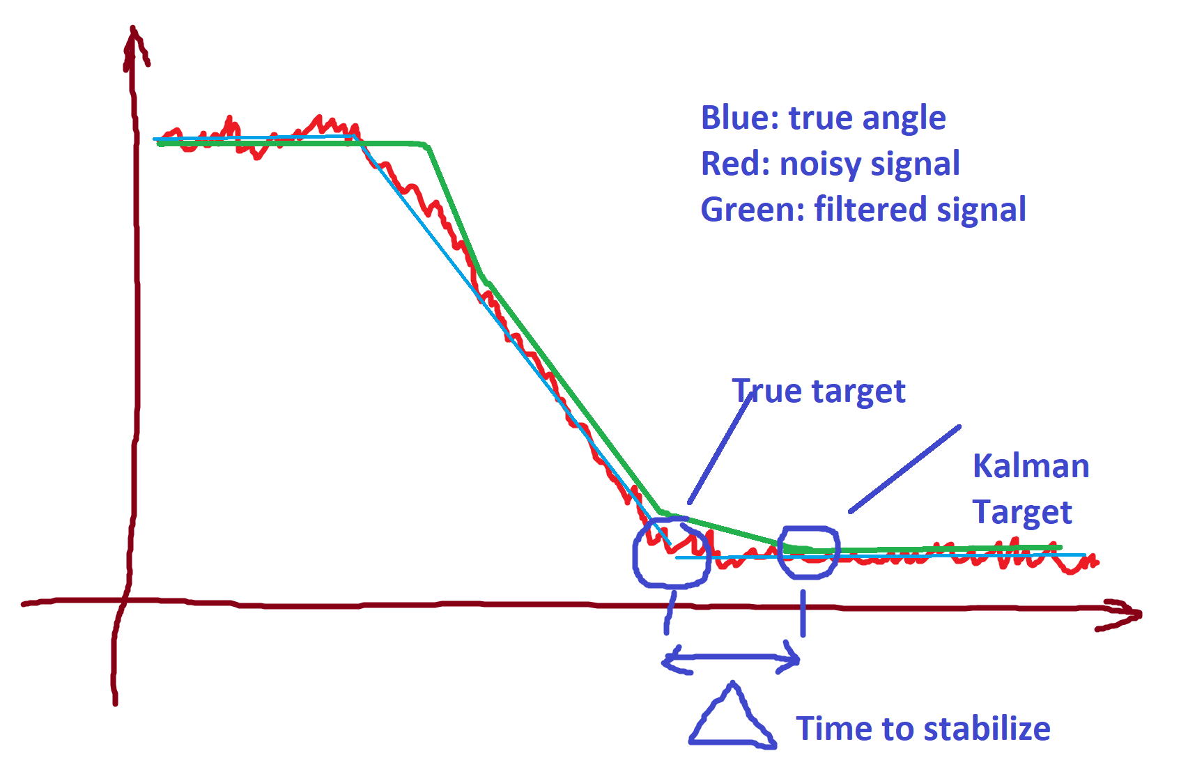
Question. Is the speed trajectory important? I mean, is the speed you get to the target important or just the X/Y trajectory? The reason I’m asking is that you can apply an ultrafast 1D Kalman filter to the angle to remove the sensor noise. Downside is that you will end up with an S-curve for the speed vector, so as long as the speed is not a constraint, you may wish exploring that angle.
My understanding of stepper motors is rather primitive but I do know they do rotate kind of very slow so speed may not be an issue here, unlike trying to control a motor rotating at 10krpm.
Also, some of the advanced 14-bit AS sensors have a pretty sophisticated error and noise correction algorithm built in, have you explored those? AS5047P have that, they call it DAEC (dynamic angle error compensation). I see above that you use AS5147, I’m a bit surprised you get such high error.
The theory is that sensor resolution must be high enough to approximate a sine wave over the different motor leads. Sensorless motor control is possible with only only 6 states per electrical revolution (2.6 bits), although that mode of operation isn’t intended for low-speed control.
I downsampled my 12-bit sensor + 20 pole pair motor to 6 bit (1.7 bits per electrical rotation) and it went poorly, the motor was noisy and occasionally got stuck. At 7 bit (2.7 bits per electrical revolution) positioning was works but the motor did vibrate more than usual. At 8 bits performance was better, and 9 bits (4.7 bits per electrical rev) performance was basically indistinguishable from the full 12 bits sensor resolution. My testbench is a linear rail with belt drive, I used my hand to gauge the smoothness of the movement. Not very scientific but it works.
I don’t think you’ll have any problems running a 50 pole motor with a cheap 12 or 14 bit sensor. With the AS5600, all 12 bits are usable at low speed (<3000 erad/s in my testing). The AS5147 you have should significantly outperform the AS5600 on all specifications.
Motor torque is proportional to current. At 0 speed and 14A, power = I^2*R = 18W of resistive losses. It will only draw this much power when FOC decides it’s necessary to hold position. When moving, power draw is higher but most of that power is actual work (=force * distance), not resistive heat losses.
Have you tested your steppers? I tested some (2) china steppers with a pololu stepper driver and got only half the advertised torque.
Hobbyking has sealed bldc’s intended for dusty environments such as the Turnigy SK8 6354-140KV, but they are somewhat expensive and thermal management isn’t as good as the open designs.
great stuff! the speed profile is not critical, as long as the tool speed stays in certain limits. I have to check for the tolerance band. Small tools (1-2mm) are really delicate and variations in force, thus speed, can easily break them.
When not cutting, you anyway have ramp-up/ramp-down speed profiles. During cutting, the speed stays constant. For home applications, you talk about 5mm/s to 40mm/s, depending on material and milling tool.
For AS5147 I refer to the SimpleFOCsource code where two bits are thrown away. This is also discussed and implemented here: A low cost modular actuator for dynamic robots
By the way: that source does also a LUT transformation to compensate for non-linearity. Might this be an improvement for SimpleFOC ? Needs a lot a MCU resources, so maybe only feasible on STM32.
Yesterday I did a little test by printing out the raw angle register value which should be DAEC corrected.
And the 14bit values look quite stable, at least when speed=0.
If I had a high-res optical encoder I could plot the values against that reference to check for non-linearity and noise.
more interesting stuff! I love it! I just answered @Valentine regarding AS5147. Adding your details could mean that on low speeds, which are in the focus of CNC operations, the sensor is good enough, maybe even 14bits when I change the code and eventually add a Kalman filter. On higher speeds, when not cutting, the precision during movements is not important, as long as the absolute, final position after the move is perfect.
Regarding torque: I was thinking about exactly that - I need the full torque also at speed=0 to keep the position under all circumstances. If FOC reduces the current, the forces could push back the axis out of the commanded position. Of course FOC will then detect a deviation and move back, but then it is too late - the piece your are milling could be crap.
With my old microstepping controller the NEMA17 ACT motors get really hot, as the current is kept high to get the holding torque of about 0.5Nm at 2x2.5Amps and 1.3Ohm, thus burning 15W.
I don’t understand yet how to get the max. torque at speed=0 with FOC.
The current is more in the range of 0.4A@12V supply. With 2V nominal voltage this should be 12/2 * 0.4A = 2.4A instead of 5A. Probably the L298 bridges 2*Rds must be considered, not only the 1.3Ohm per coil.
I have not yet measured the torque - simply had no idea how to do that. Came across Measuring stepper motors some days ago.
Checking the sealed bldcs.
What’s that in terms of RPM on the stepper, before your whole drivetrain?
if the motor is disabled (i.e. simpleFOC isn’t trying to command anything on the phases) the sensor should be completely stable, except for what I’ll call “static noise” or “background noise”. When the motor moves, it has more noise, the faster it moves the more the noise gets. The AS5147 has the DAEC to combat this, as you have noted, but I believe it is always a tradeoff of precision vs. speed.
With slow enough movement and good sensor lines I would expect you to get close to the full precision of the AS5147 - it’s not a cheap sensor…
There is also the “noise” (not really noise) caused by the reaction of the PID algorithm to the sensor noise or sensor delay. Obviously you try to tune the PID to get rid of any oscillations and stay close to the commanded value, but it’s inherently different from the open loop micro stepping approach.
I’m not sure you can do what you want but I’m also not sure the stepper does this either…
At the moment simplefoc is trying to control the voltage/current to reach a target position and velocity. So you could command 0 velocity (or better, a fixed position) and then the motor will hold this position, meaning it will oppose motion from this position. So the problem you describe would occur, I think. How much it would actually move from its holding position would depend on the “stiffness” of your PID tuning, and the delay on your sensor, at least that’s how I see it.
I am not sure “holding with maximum torque” is actually something you can do… I guess you can stop the commutation at a certain value, and apply those PWM levels to the motor continuously. Whether this results in a more stable position and more holding force than the PID, I doubt. Maybe one of our members who knows more about motors can comment on this…
I think Ben Katz says in his paper that the last 2 sensor bits are noisy. If you take multiple measurements (assuming error on successive measurements is uncorrelated), you may be able to get the full 14 bit resolution even if individual measurements only have 12 bits of entropy. Some sensors do this deliberately to add accuracy, if the noise is well-behaved you can get more than 14 bits of resolution out of a 14-bit sensor.
It is not possible to have the full holding torque at zero speed. Angular acceleration = torque / moment of inertia. At speed=0, angular acceleration must be zero therefore the net torque must also be zero. If the work imparts a dynamic force on the motor, the motor must move slightly. The motor controller can then observe that the sensor moved, modify the drive parameters by driving the q axis to the maximum current (+ or -) to move the motor back to the desired position at full torque. But this can only happen after the motor deflected in the first place.
The maximum deflection depends on the tuning of the motor parameters and sensor resolution. I did some back-of-the-envelope calculations and a maximum deflection below 0.05mm sounds very reasonable with a 14-bit sensor and 1cm radius pulley.
SimpleFOC does not support non-linearity correction for sensors, but this feature is not particularly difficult to implement.
The Kalman filtering will slow down the speed with which you approach the target. Not sure how this impacts your design, just pointing out you won’t have faster but slower approach.
Could you please point me to the exact line in the source code where this happens?
There was a small example of 1D Kalman filter optimized for embedded applications. Again I have no idea how applicable this is to your case.
My GT2 belt driven mill has these settings:
steps per millimeter: 80 ( 1/8 microstepping, 200steps/round NEMA17, makes 1600 steps/round. One round moves the gantry 20mm forward (20 teeth pulley, 2mm pitch belt, 2:1 transmission ratio by belt/roles layout )
Max. speed is set to 1500mm/min (for jogging, not milling)
Max. acceleration is set to 10mm/(sec*sec)
So my example of 5mm/sec would translate to a quarter round per second.
I agree that regarding torque the challenge seems to be the PID tuning. I learn that one must tolerate at least a very small position deviation before the torque goes up from a basic value in order to compensate for the position error. This is a fundamental difference to micro stepping, where the position is held by applying brute-force Imax. The terms holding torque and detent torque seem to make less sense when running a stepper like a BLDC motor.
I can’t imagine stopping the commutation is the solution - by which criteria should it start/stop ? Before I apply force the electrical angle stays constant, so this is what we want. If just the PWM duty cycle is high enough to drive 5A through the motor, the maximum brake momentum (my wording) is applied so that there is no need for the control loop to act against position deviation.
During approach and departure to/from this fixed position FOC algo is ok. Either one could create an artificial stepper behavior when speed=0 by having the right PID values (or maybe an extra parameter set when speed=0), or we need a kind of hybrid FOC/stepper algo - just brainstorming.
ToDo: How and how high can this basic FOC current be set ? Is it just controlled by the Rphase value? I still struggle understanding the source code in terms of what goal takes precedence over which other.
should do the trick. That will max out all phases, and won’t change until you call setPwm() again, disable the driver or re-enable the motor. Not sure it’s a good idea though! Set the voltage_limit low enough!
When reading the Angle Register:
Bit15 is the Warning Bit (MSB)
Bit14 is the Error Bit
Bit13:0 is the Angle
line 145 in MagneticSensorSPI.cpp:
register_value = register_value >> (1 + data_start_bit - bit_resolution); //this should shift data to the rightmost bits of the word
const static word data_mask = 0xFFFF >> (16 - bit_resolution);
return register_value & data_mask; // Return the data, stripping the non data (e.g parity) bits
As data_start_bit=15 and bit_resolution=14, register_value is shifted right by two. This removes the two lowest bits. Was this really the intention ?
In the next step the warning and error bits are masked out, which are now at position 13:12.