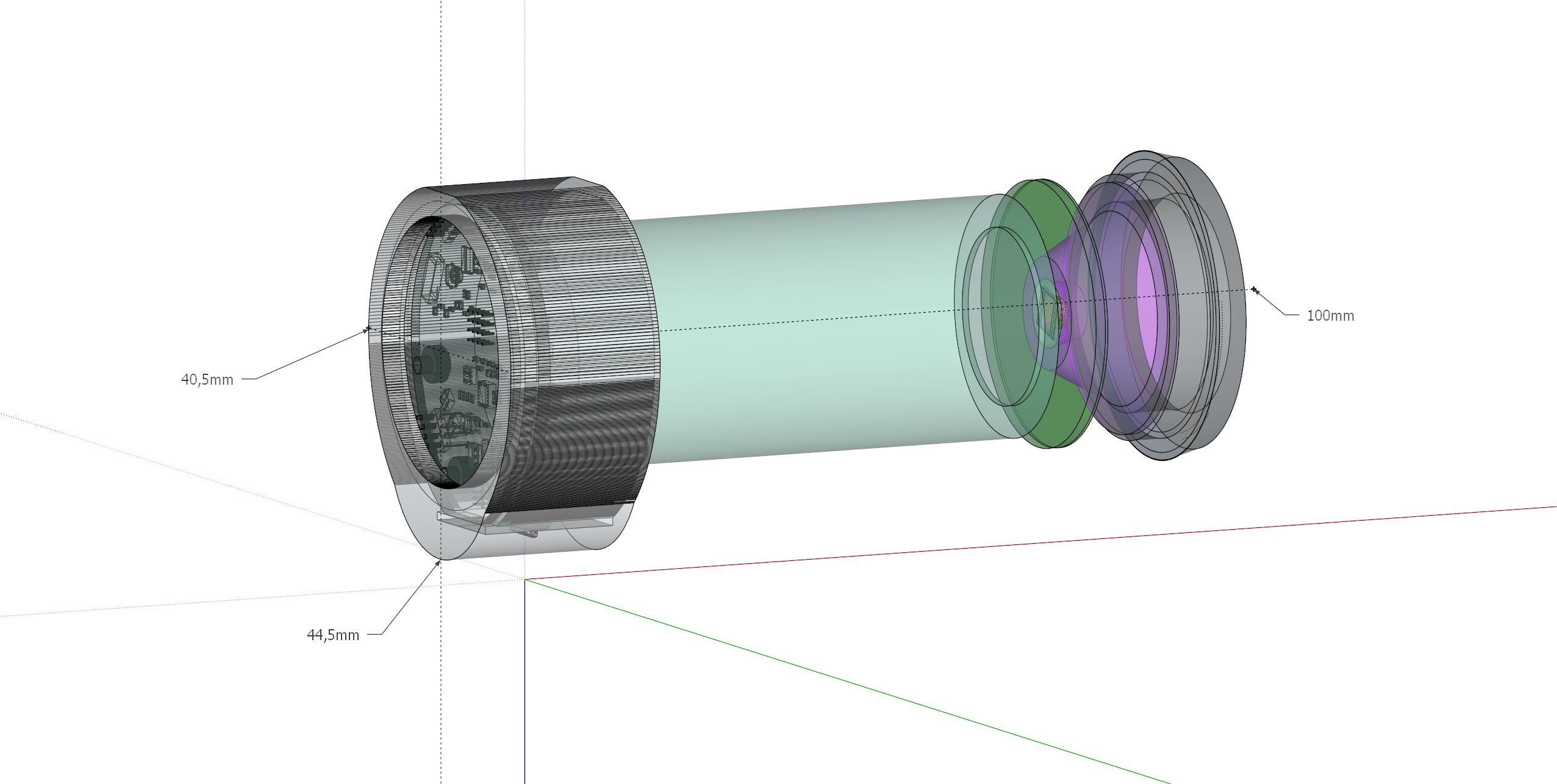
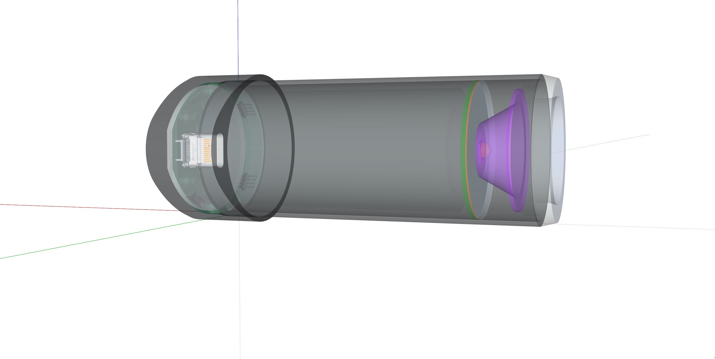
Using stainless steel pipe OD 38mm, Thickness 1.2mm = ID 35,6mm for 32mm Ø 32650 battery, and wires for LED, plus battery ground for system and charge circuit. The battery will need some soft padding to fill the void.
Some may think the screen should be angled, to ensure a better viewing angle when biking, and the light is on to illuminate the road. But in that scenario you want your eyes on the road.
A 3D printed clip on the cable will make it possible to secure it with a oring.
To change the battery, there must be a wire attached to the LED PCB, long enough to take it fully out off the way. Going into the field with this screen, connected to your phone via BLE, the battery on the phone will last very long, likewise the flashlight / connected device / motion sensor, will have a large battery pack and the possibility to change batteries, pre_charged. Further the devise can charge the 32650 batteries with a max current of 1500mA(temperature dependent).
Potentially the device can detect a fall and if enabled, send a help message, if not turned off within a while, sending the exact GPS coordinates from the phone, to who ever is listed as the emergency contact.
I’m not sure I understand everything in your project, but it sounds cool nonetheless Let me know if you need help on the software side (device and phone).
It depends on what you want to achieve:
6-axis IMU allows for linear acceleration measurement, angular velocity measurement and (to a certain extent) angle computation.
9-axis IMU allows for more accurate angle computation, and also allows for a compass feature.
BLE+smartphone gets you a GPS, allowing for position and speed measurement, knowing that smartphone GPS provide data at at most 1Hz (if you want more, you’ll need to embed a GPS in your device).
Here lies a general and tough challenge: how to turn IMU data into actual added value for sportsmen. I know for a fact that many people are working on this at this very moment.
I will keep the 9-axis IC. At one point I was considering a 6-axis since there are newer versions with 3v logic (the 9-axis only has 1.8v logic). But this was only because the 1.28inch screen was limited to 3v logic. With this 1.32 inch screen (360x360 QSPI), it is only the i2c lines for the Cap touch IC which need translating.
If the devise is used for trekking/pilgrimage/migrating purposes, then the compass will be very nice indeed.
I’m not sure I understand everything in your project
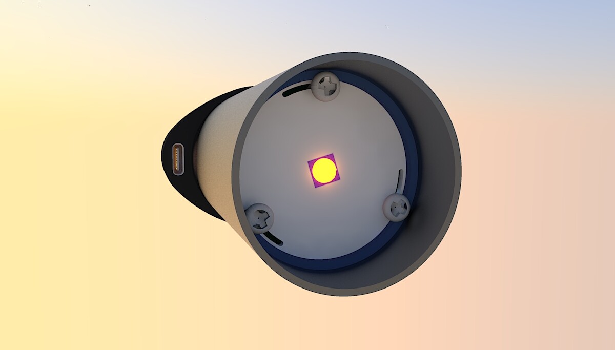
This project is linked to the motor controller project for a eMTB I have been working on. It is basically a advanced HMI for ebikes with a integrated RGBW ( 4 separate diodes, 1amp each, in a 5x5mm package) diode and 32650 battery. The motor controller setup will be a direct drive run through a 11 to 1 gearbox (+/-) to facilitate the use of high rev sensored outrunner.
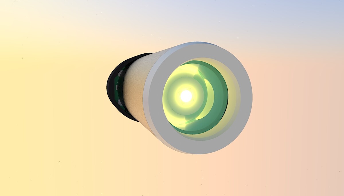
Mixing the RGB (Red, Green, Blue) should produce a white, depending on the mix ratio. So running the headlight at low intensity, the single white LED could be used. Having the color´s will just be a added bonus, but will have a use case. Like signalling.
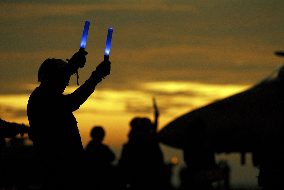
If you where to use it inside a sword like devise, with a polymer “blade” which will despurse the light, kindoff like the non-transparent diodes, diffuse, you could then have a VR motion tracker and the 9-axis data to represent the sword in VR
You see Ray´s sword, its a two hand sword. Other Jedi has one handed swords.
In combat the Jedi is relentless and lethal. Sometimes they move with out of this world speed, which should be part of the VR game experience. Unless the droids have a shield, only a single strike or laser should end them. Catching the laser beams and to shoot them back is the whole exercise. Like that first pingpong game. So can we dodge bullets. When you are ready, you want have to
Is there still room on your deign to have a speaker? I think it’s of utmost importance that the lightsaber can produce sound (using the IMU to create the distinctive humming)
If you are in VR you could have a large 21 inch bass attached to it.
I have thought of a small motor for vibration. Sure, that can be done and there is room. Just have to find the exact part and datasheet. Having the handlebar buss, if there is a warning is maybe over the top for bike application.
I believe a knop for moving inside VR is just as important, But that will require some extra thinking to the circuit (maybe have it as a i2c breakout board for wired integration into the final sword assembly. Which would require drilling holes for signal and power lines or have the holes integrated into the hood). I guess it will be on the other hand with the VR controller for the specific platform. You could also have a custom VR glove with some kind of sensor for measuring finger bending and some buttons inside the palm. If you wanted to integrate a small vibrater (like the ones in phones) it would probably be located in the space between the battery and the LED PCB.
Moving the FET´s to the second layer makes room for some larger, more capable switches, for driving the LED´s. This opens up the use case for larger 2 wheel vehicle’s. Like road approved front headlight and turn signal in same package. Plus the benefit of the screen for speed, rev and such useful data.
Let me know if you need help on the software side
I have 10 nrf5340 rev 1 samples here which I intend to make use of. If there are others who would like this screen and MCU (nrf5340) to work on. Let me know. The price will be for components and PCB. Maybe I should make a crowd campaign at some point. Guess proof of concept is part of that.
having the 2nd layer opens up a whole range of cases for custom shields with motor control. Maybe all you want is a connector board for connecting drone BLDC controllers, running SimpleFoC, in which case you probably want a external antenna, depending on the range of the chip antenna. The Nordic nrf5340 does have long range BLE. Im unsure about, if you can use the uRf connector used for tuning the antenna as a external antenna plug, but I guess if it is already 50ohm, then it will gladly transmit on the 2.4 band. The FCC and CE documentation should include this external antenna in the test, unfortunately it is not just pick and run. Maybe several antennas could be tested, as to document, that any 50ohm antenna will be within the standards, if that is the case.
Im considering, if it is better to integrate a vertical usb_c plug, and have it sit right there in the gab between the 38mm cannister and the enclosure/hood. The hood will be bonded to the cannister with some high strength low viscosity glue. This would orient the usb_c cable in parallel with the devise, which will tugg it under the handlebar (if mounted under the handlebar)
Found a good vertical USB_C receptacle. Since it will be mounded to the 2nd PCB layer, in a sense it will be optional. There are many other ways to connect USB devises, PogoPins is one. The plug has 30u gold contacts, so its durable but also a bit pricey compared to other parts. Had to increase the bulge in the cap/enclosure to make room for it. Most likely there should be a “cover”, which will be bonded to the enclosure, when gluing in the 38mm canister.
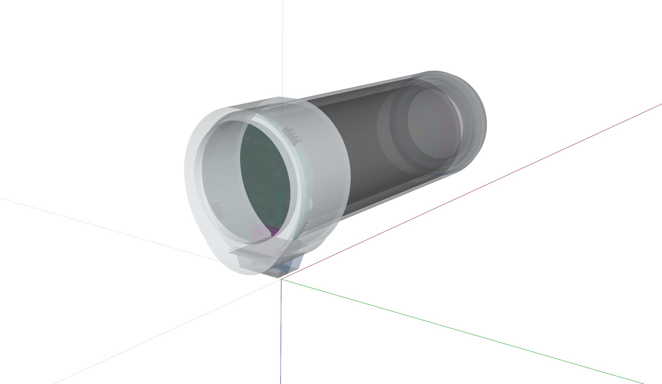
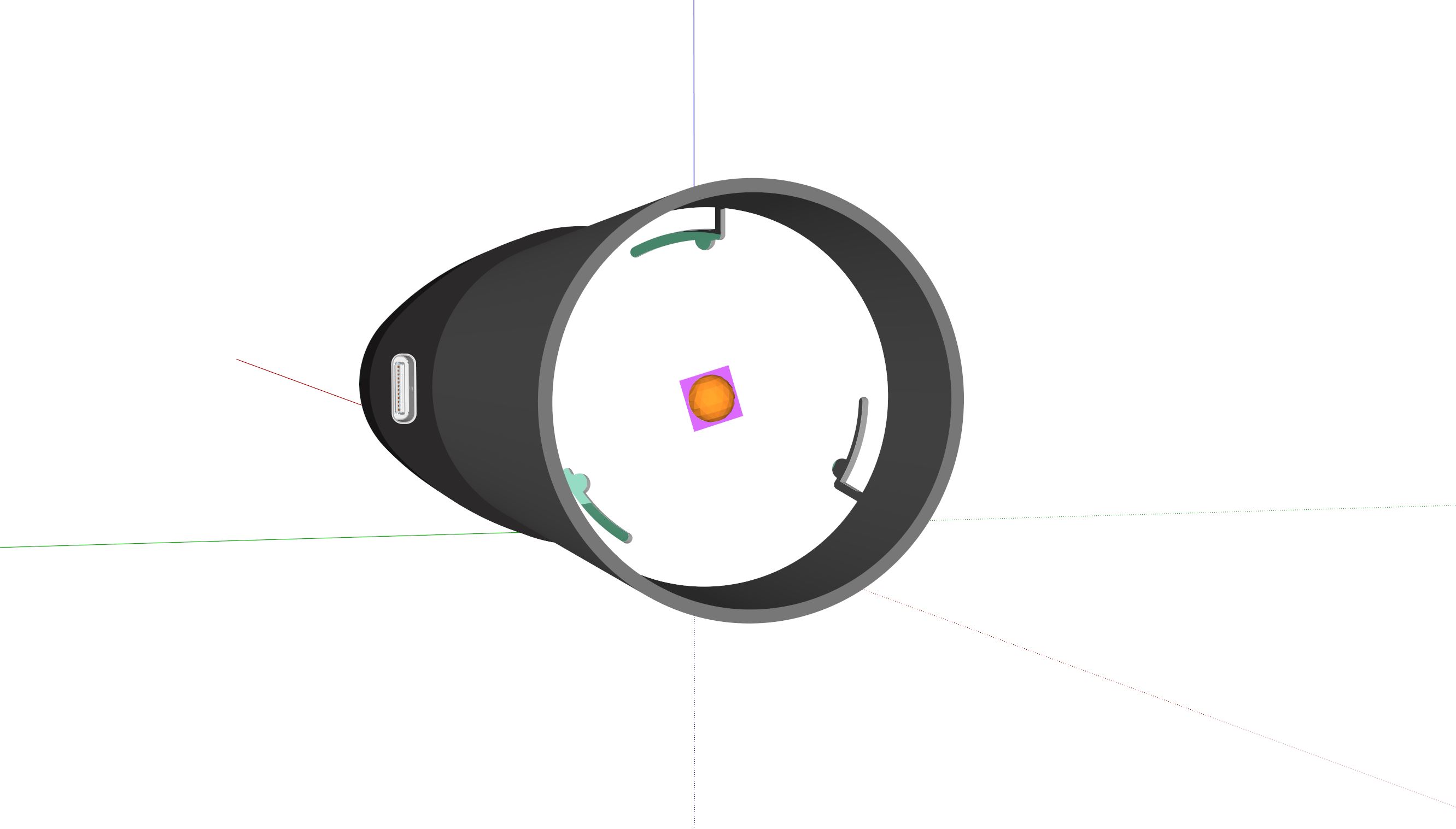
Wedging in the LED PCB, using small self_tapping screws, will make it possible to seal the end_cap with a o-ring or two. No need for threads or glue. From the LED PCB there should be anchors for the end_cap to grab onto. The distance from the LED PCB to the end_cap will need to be precise. Wires must be mounted top side, since the LED PCB must be copper or aluminium MCPCB (Metal Core PCB). By wedging in the LED MCPCB, heat transfer from the LED MCPCB to the canister will be greater then heat transfer from LED MCPCB to battery. One could ad a layer of insulation between the battery and LED MCPCB, as long as there is contact for GND connection.
Using a 3D printed spacer between the battery and the LED MCPCB, essentially the 3D Printed part could be the anchor. One could have a braided copper spring/wire/mass connecting the back_side and the battery (MCPCB is copper or aluminium == GND).
M3 bolts. Holes are cone shaped. Contact should be made by compressing wires wrapped around the inner circel. We want to avoid to much heat leaking into the battery, maybe its better to have the GND contact for LED MCPCB in the periphery, where the cooling surface is closer.
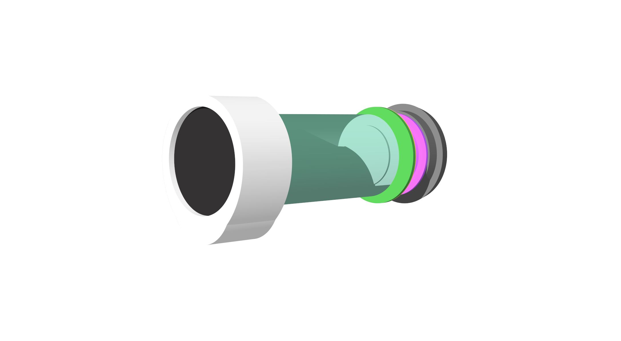
Found the LED lens part. Having the dimensions does help. This is a PMMA lens, so it is a plastic and should probably be coated for outdoor use (UV protection) or have a hood. Since it has these cutouts on the base, it makes it possible to make a strong bond. It is meant for spot´s, with a FOV (Field of View) of 15 degrees.