Hello!
I needed high current board for FOC applications, while Im waiting for SimpleFOCDrive I’ve designed custom board based on SimpleFOCDrive.
I’ve replaced some elements with those that I could get faster:
DRV8320 → DRV8323
BSZ0904NSI → NCE3095K (I’ve tried to get the most similar MOSFET and make some changes in the initial driver configuration to fit difference between these mosfets)
The datasheets for these elements:
DRV8323
NCE3095K
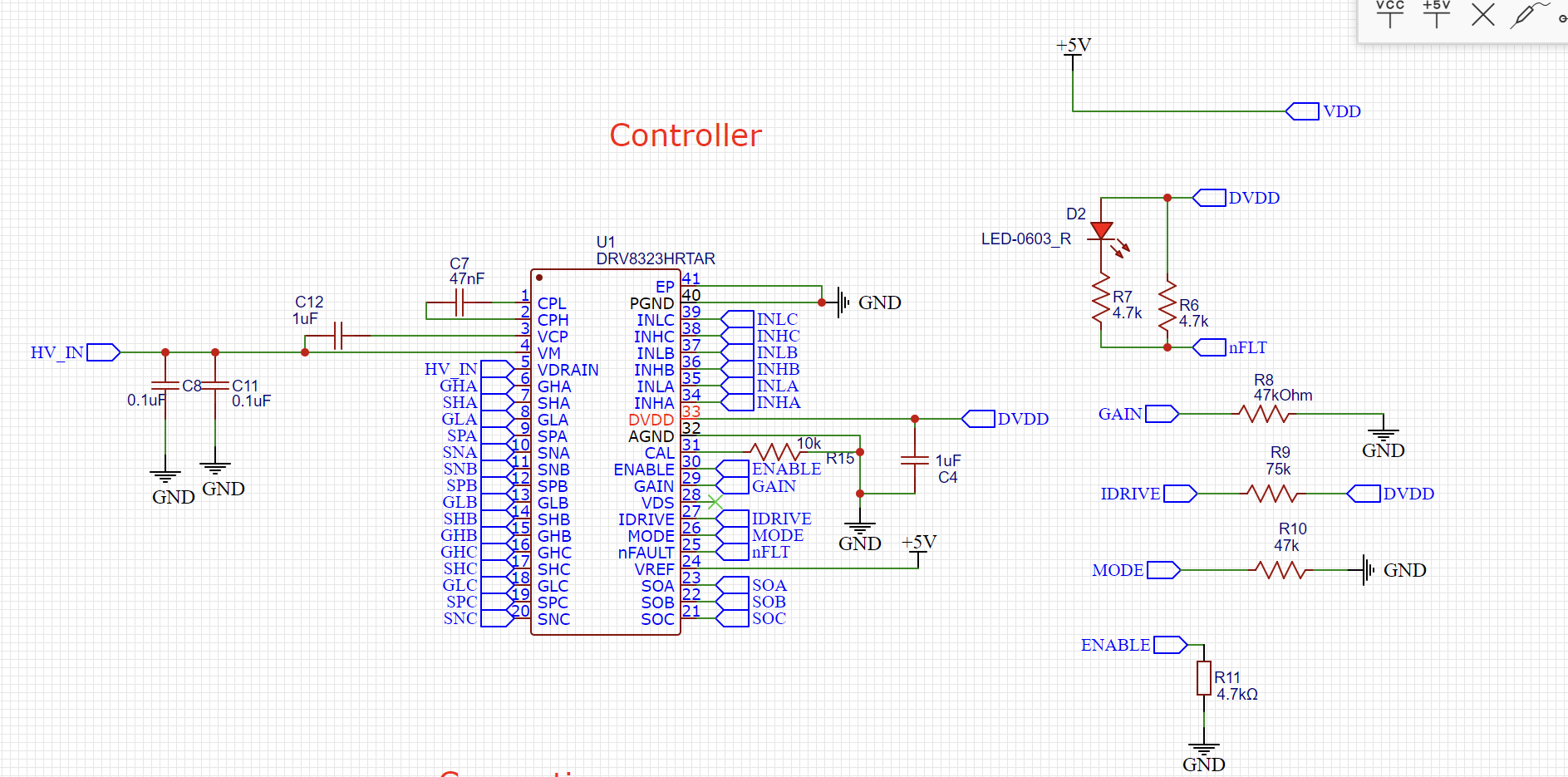
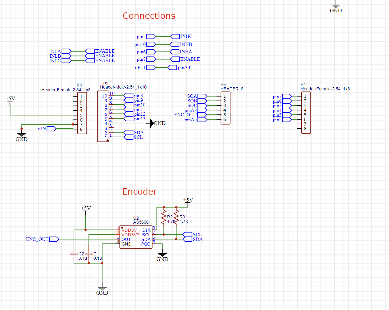
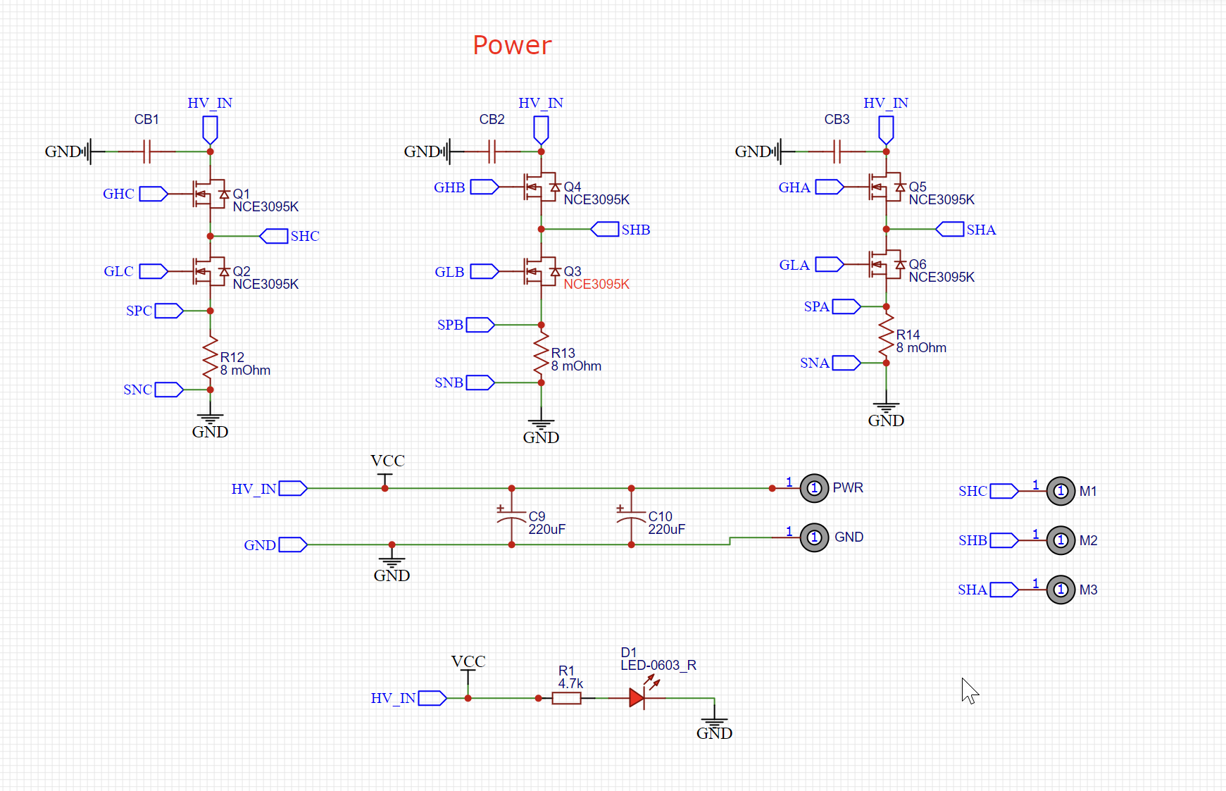
Schematics for my board:
I’ve also checked other topics about DRV8323 and schematics there look quite the same (or at least close enough)
But now I’m testing my board and it isnt working (simple driver_standalone test from simplefoc lib to get constant voltage on the phases).
I’ve manufactured it myself and it turned out a quite messy, but I checked connections with multimeter and it appears to be fine. Although I cant really confirm if DRV connected to all the pads as it should because I cant reach chip pads.
Anyway, I would greatly appreciate if somebody could give me any tips on finding the problem.
Right now main suspects to me are:
- Incorrect mosfets
- Bad connection of the DRV microchip to the pads
- Mistakes in schematics
3 Answers
3
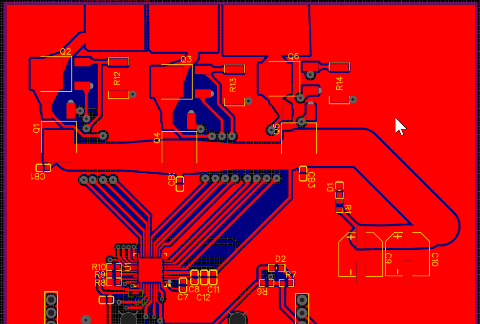
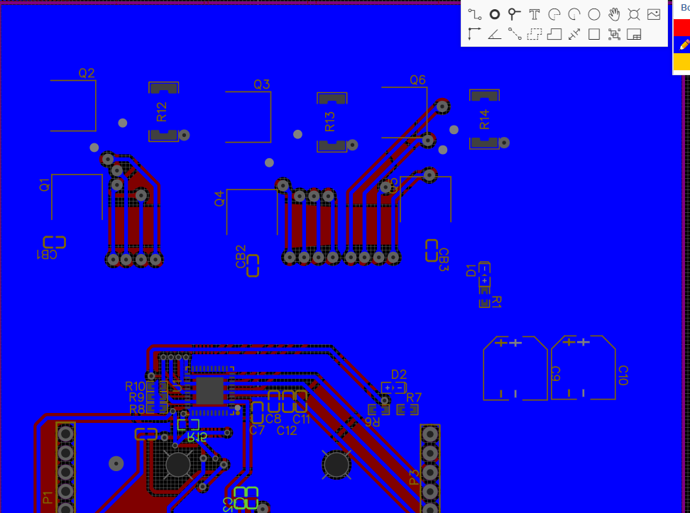
Also here is my layout for driver. Image cropped cuz nothing important is down there, only headers and encoder
I use a cheap USB microscope to inspect QFN solder joints.
Usually there will also be stray solder paste balls all over that are invisible to the naked eye, so don’t use lead paste or they’ll contaminate your house. With lead-free, you can flood it with alcohol and scrub with a toothbrush to clean it up, and gently prod any stubborn ones with an x-acto knife. But brushing scatters them around the room, so definitely don’t do it with lead.
Ok, I’ve remade my driver with slightly better manufacturing process, now its working, but the DRV chip itself has suspiciously high temperature (not insanly high, but for the 1V motor limit its already like 60C)
Im not sure what it could be, as for now I think it might be something with the current sensing since there are lines that are going from phase output to the DRV directly in parallel with schunts. If somebody has any thoughts on that I would like to hear it, thanks!
I used 8mOhm resistors and gain 10, while my motor have 19.5Amps max current. I actually tried to switch to lower resistance (3mOhm) and higher gain (20) in order to have more space for motor current, but I think DRV became even hotter so I might not correctly understand current sensing in this application
Thank you for your advice, I'm definitely gonna buy one and watch out some lessons about QFN soldering. I've tried to re-solder it today and got some weird outcome: full voltage on 2/3 phases and 0.6v on third one. I've inspected the board and found some shortenings between PWM inputs and enable, I fixed it and out mosfet voltage disappeared again. I guess it is indeed bad soldering due to poor manufacturing. I was using acrylic paint that I was burning with the laser, now I'll try to re-manufacture it on the cnc fully, check the results and post update in this topic
– lexan253