I am currently designing a PCB with the TI DRV8317 driver (similar to DRV8316 but lower power) and an STM32G431CBUx. The motor is a 12V BLDC with 1.3A of stall current and hall sensors.
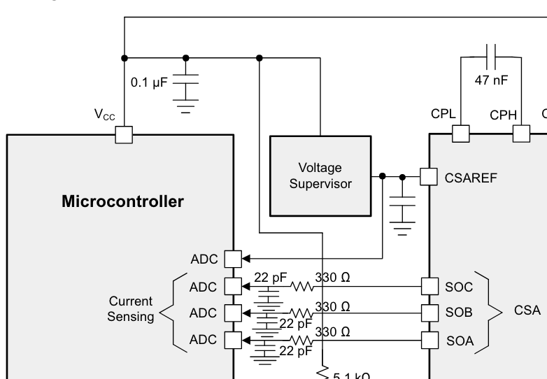
For the current sensing the driver has a CSAREF pin which functions as the “Current sense amplifier power supply input/reference”, so an external voltage reference (VREF) can be provided through CSAREF pin.
In the Figure 9-1 of the datasheet, they also show the use of a ‘voltage supervisor’.
The STM32 also has a VREF+ pin, and the datasheet mentions that "VREF+ is the input reference voltage for ADCs and DACs. It is also the output of the internal voltage reference buffer when enabled, which supports three output voltages: 2.048 V, 2.5 V, and 2.9 V.
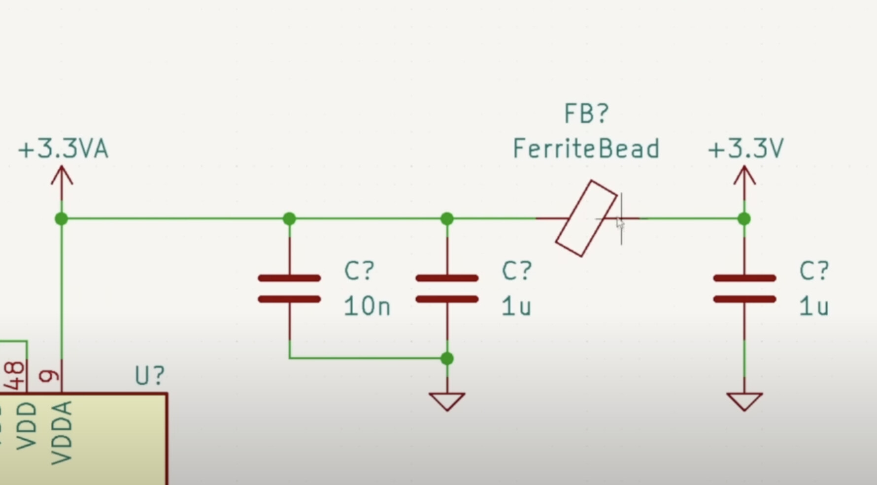
I was planning on having this circuit for the VDDA pin on the STM32:
Since this is all quite new for me, I’d very much appreciate some guidance on what would be the best approach for the voltage references. Should the CSAREF pin of the driver be connected to the VREF+ of the STM32? Should there be any more filtering? Thank you
I would connect it to the 3.3VA net, and include the bypass capacitor to AGND as recommended by the datasheet.
You can of course have it operate in a more limited voltage range using the VREF output or some other reference voltage, but why limit it?
You can also include some optionality in your PCB design by having some solder jumpers, then you choose to connect it to either VDDA or VREF with a 0ohm resistor or solder bridge and experiment with the different options to see which is best.
Should the VREF+ of the STM32 then also be connected to 3.3VA?
That’s a good question… I’d have to dig into the Datasheet…
Let me check.
https://www.st.com/resource/en/application_note/an5690-vrefbuf-peripheral-applications-and-trimming-technique-stmicroelectronics.pdf
So I would say yes, if using an external reference then tie both VREF+ and CSREF to that reference.
But reading more about the VREFBUF it’s actually pretty cool, and you can use 2.9V range on the G4 MCUs…
And in this setup it doesn’t seem hard to use either, so perhaps I’d change my advice and say do use it, or do the solder jumper thing so you can test out both…