Hello,
I am facing issues using the DRV8316 in 3xPWM mode to drive a BLDC motor.
The overcurrent current protection (OVC) always triggers in one of the three channels and put the driver into fault condition. This event happens at start-up a lot but also when the motor is spinning already fast. Also, OVC error comes very often with overtemperature error but I am not able to tell which one triggers first.
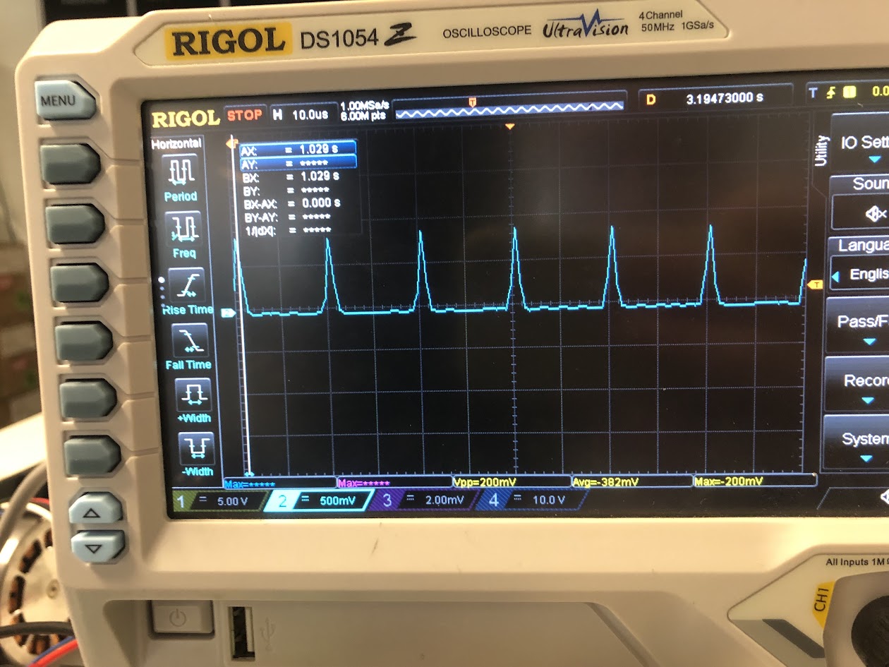
To eliminate any motor control problem I did tests with a single resistor to dissipate power between 2 driver channels. You can see below the resulting current of PWM injected into the resistor. The peak value of the current is ~ 8 A.
I know the chip is limited to 8A peak but the peaks on the scopes are very short (<5µs) resulting in an average DC input current much lower. I have tried this experiment with 9V and 18V DC input supply but the result is the same.
With the following setup, is it normal that the chip goes into fault ? Have you experienced any similar issues ?
Do you know what is the point to set OCP_LVL register to 16A or 24A if the OCP protection is actually triggered by such peaks ?
I’ve got my own custom driver board using DRV8316C and it is not normal that the chip goes into a fault condition from drawing 8A. My setup also uses 3x PWM so that is likely not the cause. My OCP_LVL is set to 16A, and it does not trip during normal operation. I am able to draw 8A (peak, 5.6A RMS) from the chip continuously for about 2 seconds before it goes into over temperature protection, however if your PCB has bad thermals or the thermal pad is not soldered properly (happened in one of my earlier boards which I soldered by hand) it may trip much sooner. I am able to draw 5A (peak) for at least 1 minute without overheating. Can you try with multiple chips to rule out any issues related to a faulty chip or bad solder connections?
The OCP has tripped before when I was using Sinusoidal control instead of FOC, and the input command was ramped too fast causing an overcurrent. It is likely the overcurrent protection tripping is due to a problem with your control algorithm. Try to use FOC if possible because it regulates the current and is likely to fix the overcurrent issues. Could you tell me what algorithm you are currently using to control the motor?
I suspect the reason for the OCP trips in your resistor test because the rise time of the current is very high, which from the picture is approximately 2us to rise from 0A to 8A. This is very high and could be causing the overcurrent faults in your test. I suggest you redo the test and connect an inductor in series to simulate a motor better in these tests. You can use your BLDC motor as an inductor if you don’t have one lying around. Could you also explain the method and equipment you used to determine the peak current? Cheap current clamps may not have enough bandwidth to measure this kind of current accurately.
The OCP deglitch time might also be the cause of the overcurrent trips if it is set too short. Can you try increasing it (0.6us setting works for me) and seeing if the OCP fault goes away? There is also the option to disable the OCP entirely by setting it to report only mode, if you try this be aware you might kill your chip.
I have not experimentally verified the OCP tripping point, but according to the datasheet it should be between 10A and 22A for 16A setting, and between 15A and 30A for 24A setting.
Hi Andrew,
I just did the same experiment with a motor but got similar result at the same level of current around 8A (see picture attached).
My commutation stategy is an homemade FOC but actually the DRV fails at startup.
The board I am working with is soldered by hand. I got similar behaviour on other boards that were also soldered by hand.
The current probe that I am using is the Elditest CP6220 which seems good enough for that.
I am planning to redo similar experimentation in the coming days with the evaluation kit provided by TI and also to play with the deglitch time even though I am not hoping much from that side.
I will keep you updated.
If the board is soldered by hand, how did you manage to solder the thermal pad? I have earlier revisions of my motor driver which were hand soldered, and the thermal pad was not soldered correctly most of the time, so the motor drivers kept going into overtemperature. I would suggest reflow soldering the chip which will reliably solder the thermal pad in my experience. I find that a reflow oven works much better for reflow soldering than a hot air station, I have tried both methods in the past.
I think the chip goes into overtemperature which causes the overcurrent to trip, as the overcurrent threshold decreases as chip temperature increases because the mosfet on resistance increases with temperature, and overcurrent is usually implemented by comparing the voltage across the mosfet while it is turned on with a reference voltage.
It is also possible that your motor takes too long to start up if it is a large motor or connected to a big load, so you may want to decrease the current limit in your FOC settings and see if that solves the issues. 5A peak current (3.5A RMS) should be good for at least 1 minute from my testing. An alternative would be to enable the over temperature warning, and allow 8A when the warning bit is not set, and reduce to 5A if the warning bit is set.