The idea is that the magnet would be glued to the end of the motor shaft, and the driver board would be attached to the motor - with washers or a 3d printed spacer.
I have one issue so far with how I’ve setup the DRV’s sleep pin, but I can work around this for testing.
This is a 2 layer board, and this time I’ve used HASL instead of ENIG, and it worked well.
Total BOM cost in quantities of 10 is around $13.
Now I’ll have to look at @runger 's code to get SimpleFOC running!
Am I right that you’re not using the WiFi on the ESP? I can’t see any antenna…
What voltage can it support? Did you get it with 2Oz copper or more?
Did you reflow it yourself or order it with assembly?
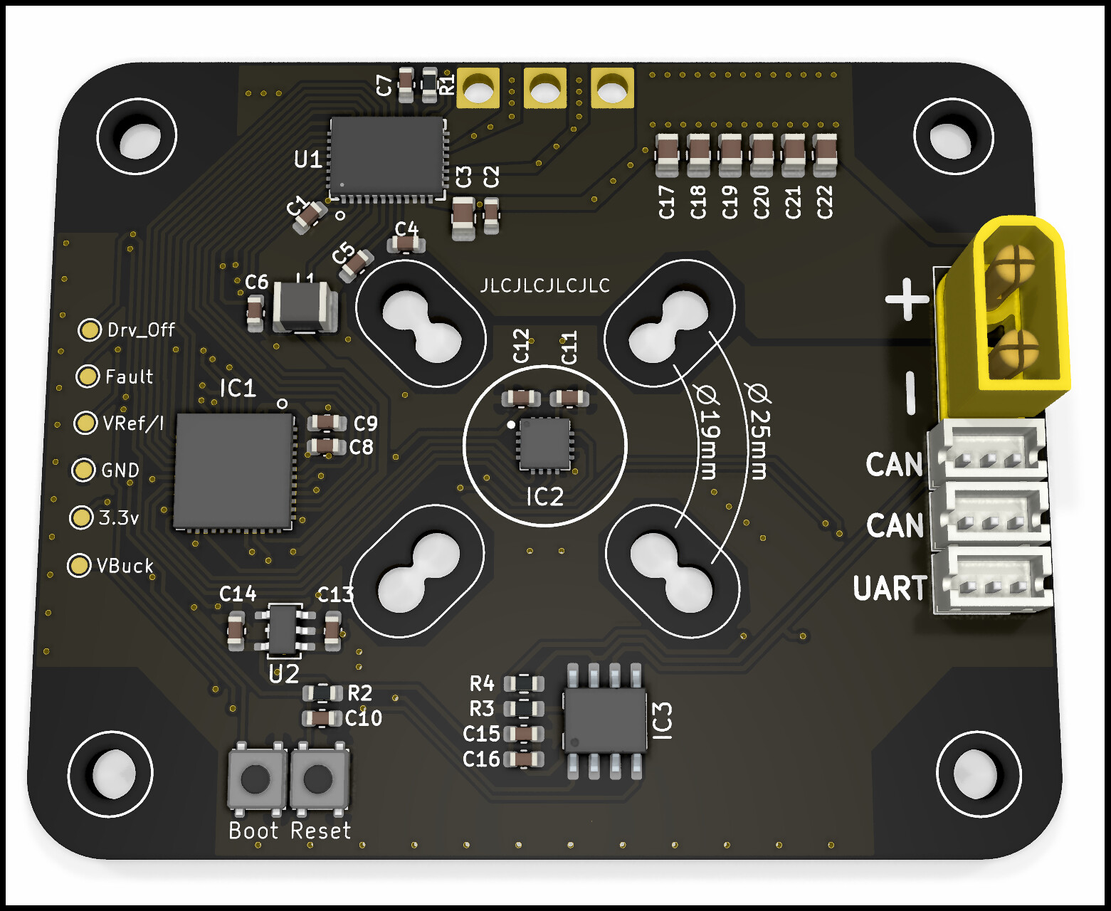
It it intended to be mounted facing the motor, or can the MA702 sense the magnet through the PCB?
What’s your bulk capacitance? Is it C17-C22? How much does that amount to?
I have a DRV8316 based design in production (I’ll post here as soon as it arrives, but it will be a few more weeks unfortunately!)
In terms of the driver code it is working well for me for 3-PWM and 6-PWM… if I know someone is using it I shall prioritise adding the other features like current sensing and fault management…
I’m also going to split it off into a separate repo.
I would expect it to get hot when driving near its current limits - are you running open-loop or closed-loop? If there is no load on the motor, there should be a big difference between FOC (closed-loop) control and open-loop control in terms of the current drawn - which will help keep the driver cool!
Other than that, I’d expect you probably need a heat-sink when driving 2+ A continuously.
Also, it depends how hot things are getting - if its 70° or 80°C that does feel hot to touch, but should not be an issue for a motor driver IC. If it goes above 100°, id be concerned, but it has OT protection so you should be fine either way.
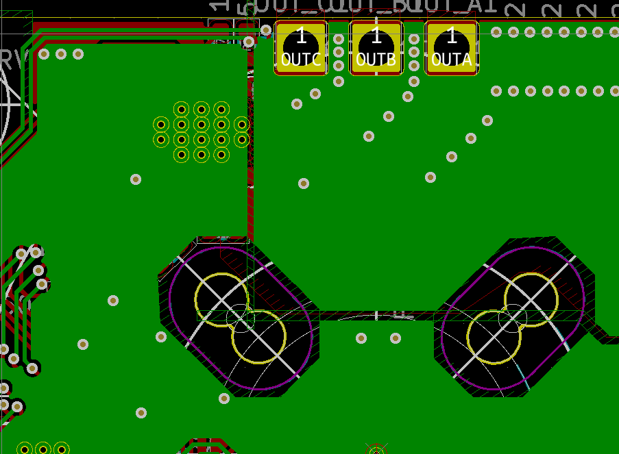
I don’t think a net-tie will help much - what you want is a large copper area around the chip, which you do have… maybe 2Oz copper would help a bit, and leaving the copper exposed, but in the end there’s only so much heat you can dissipate though thermal vias into a PCB… heat sinks (and fans) are pretty much a must on ESCs that handle multiple Amps… on Quadcopters these are never present because the quads are “self-cooling” when they fly… but on RC-cars the performance ESCs always have heat-sinks, and many have fans…
This is running closed loop. It’s cool when idle, or free running - and only heats up under heavy load.
Yes - it’s just hot to touch it, not too bad. I’m sure it’s ok at that temperature.
I’ve started design of my revision 2.
My problem is with the DRV8316’s nSLEEP. It requires a logic high, and the internal LDO and Buck won’t start up without it being driven high first. (Chicken and Egg…)
I had the MCU setup to use the DRV8316’s buck - with a small external LDO. It works fine, and reduces my component count and cost, but I can’t drive nSLEEP high…
Now instead, I will power the MCU by it’s own buck, which can also drive the nSLEEP high.
I’ve seen these sleep low things before and they are quite annoying! If you know your source supply voltage you could use a voltage divider. nsleep max = 5.7V - I suspect it’ll be on between 2.5 to 5.5V which gives you a fair bit to play with i.e you could choose resistor that work between 12-24V.
Thanks - Yes, it has a pretty wide range of 1.6 - 5.5v. I was thinking of using a voltage divider, or a zener voltage clamp. With a divider, I could get 7 - 24v input range.
But I figured that by the time I add these extra parts, I could combine them with the LDO I had powering the ESP32/Encoder/CAN, and swap it for a buck (+ 1 or 2 more parts).
The LDO was required between the DRV’s Buck and these components - because the DRV buck voltage can be increased to 5.7v with a register write, and 5.7v would fry the esp32, and be close to absolute maximum for the other two.
If only they had made SLEEP a pull down to enable pin, or given it the full range of VM. It would made the integrated buck/ldo so much more useful.
Perhaps @xcalplaxis can explain why TI went with enable high on sleep high on the sleep pin. I can understand it on other drivers but on this device with a buck, it does lead to that ‘chicken and egg’ situation where the mcu powered by the buck can’t enable the drv8316 through its nsleep pin.
Believe it or not it is for safety reasons. Better to have the driver shut down when there is no voltage present in the system. There’s a relatively simple circuit you can use to turn on the nSLEEP via a switch from VM, and then once the MCU is awake hold on nSLEEP.
We have other parts where the regulator is completely independent (i.e. DRV8323R), but on this one the regulator is very much tied to the power up sequence of the DRV.
By the way, the 5.7V setting on the regulator is intended for situations where you would want to put an LDO outside our part to generate a cleaner 5V rail. It gives some headroom for that external LDO.
Development will continue there. Let me know if that works for you. The functionality is the same for the moment, it just got moved into its own drivers library.
Hi Jason, I was able to finally order some DRV8316 chips and am planning on making a similar ESP32-based motor controller. Are your kicad designs for your driver publicly available? I’d love to take a look. Any updates to v0.2? Thanks!
Hi Jason - I have built the board but need a bit of help getting it going. Do you have an info on how to set it up with simple foc studio. Thank you for your time.