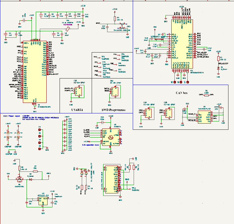
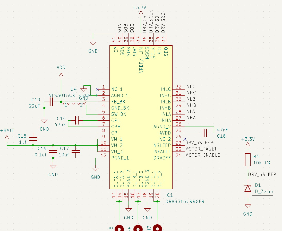
So i designed a board with drv8316 and encountered a problem with the buck of the DRV8316 by default when the nsleep pin is pulled high it should output 3.3v right?. From what i read in the datasheet it says like that but i get 2.5v only. I have attached the schematic below
Does it work when the USB is plugged in? Otherwise it looks like you’re trying to pull nSLEEP high using the output of the 3V regulator, which is powered by the buck, which doesn’t turn on until nSLEEP is pulled high by some other source. It baffles me how the hardware designers could have overlooked such an obvious paradox. Surely it wouldn’t have been impossible to invert the polarity on that pin so you pull it low to activate the buck.
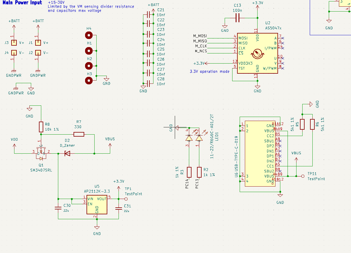
What is the purpose of the eight 10nF capacitors between +BATT and GND? Are they supposed to be 10uF for a bit of bulk capacitance?
yeah that was a typo those are not 10nf they are 22uf bulk capacitance. Also i mistakenly connected the nSLEEP to 3.3v of the regulator it should have been connected to VM. But removed the trace connecting to the 3.3v and removed the diode put a voltage divider to give the nSLEEP 3.3v still only 2.5v is supllied from the buck
Hmm, hopefully someone who's actually used it before can advise then. It looks like the configuration register has reasonable defaults, assuming the BUCK_PS_DIS bit has no effect when it's set to output 3.3v (it says elsewhere that power sequencing is only supported for buck output >=5v)
Hmm, hopefully someone who’s actually used it before can advise then.
I have used it before, and the buck worked for me.
As Deku pointed out the bulk capacitance has to be higher, but you’ve already mentioned it’s just a typo.
The “chicken and egg” problem we already discussed on discord, and you’ve tried different methods of pulling nsleep high.
The diode D2 is marked Zener type in schematics but I think it should be a schottky or just a normal diode.
The circuit around Q1, I’m not sure I agree with it 100% but it should work as long as VDD is just a small amount higher than VBUS…
At which places in the circuit are you measuring the 2.5V?
Thanks for the looking into it. I have found the issue thanks to you but i don’t know what happened the buck was indeed generating 3.3V but the output of the SM3407 was only 2.5V. I tried removing the diode connecting it to the VBUS and it worked. I don’t understand why that happened.
Is there a better way to isolate the USB and the BUCK of the DRV???
In DRV8316 i read the fault register and the fault bit is 1 but all the other registers shows no fault how is that possible? like this
00000001
00000000
00000000
The first register last bit shows that there is a fault but the other bit shows that there in no fault???
I’m glad you found it. I don’t know exactly what’s going on, but definitely you don’t want a Zener diode there.
Two normal diodes would be sufficient to isolate the power sources from each other, but depending on what exactly the goals were a power mux, load switch or efuse IC might work better for you.
Getting it right with just one FET will be tricky, I think.
yeah i tried clearing the fault with the CLR_FLT bit in Control_Register_2 Register but the nFAULT pin is still LOW and the FAULT bit is still 1. I could read all the registers and write but couldn’t figure out the issue with the fault
The fault pin needs a pullup. I don’t see one on the schematic, but the MCU internal pullup may work. Do you have it enabled? pinMode(PB10, INPUT_PULLUP); (at least I think it’s PB10, the MCU schematic image is very low resolution)
yeah you are correct it is PB10 and yes i have enabled the internal pullup for that. When i read all three status the only bit that is 1 is the FAULT bit indicating a Fault but every no other bit in all the three registers is 1. So technically there should be not fault IDK what is happening. Trying to figure it out
Edit: Or am i reading the registers worng??? this is how im reading it.
Yeah the first i did is trying out that code but the example code not getting anywhere it is stuck after Initializing... not printing the status of the driver like as it should
yeah that was a typo those are not 10nf they are 22uf bulk capacitance. Also i mistakenly connected the nSLEEP to 3.3v of the regulator it should have been connected to VM. But removed the trace connecting to the 3.3v and removed the diode put a voltage divider to give the nSLEEP 3.3v still only 2.5v is supllied from the buck
– KAVIN_GHmm, hopefully someone who's actually used it before can advise then. It looks like the configuration register has reasonable defaults, assuming the BUCK_PS_DIS bit has no effect when it's set to output 3.3v (it says elsewhere that power sequencing is only supported for buck output >=5v)
– dekutree64