DRV8302 + Tarot motor -> Control type: Voltage : Magnet polarization problem

Dear FOC-Community,

First of thank you all for the great library and also for the great website with lots of information!

Side node: I am building a robotic dog and I am more familiar with the mechanical side of things than the software side, so this is all quite new for me.

My goal is to have position/angle motion control. To achieve this, I used the following setup:

Hardware setup:

  • Microcontroller: Nucleo 64 or Arduino Uno
  • BLDC Driver: DRV8302
  • Encoder: AS5600 Magnetic encoder
    -Motor: Tarot 4108 ( Internal resistence : 135mĪ©)

With this setup, I achieved the following things:

  • Working Open loop velocity control
  • Working magnetic sensor

So the following step after this was achieved was closed loop voltage control and here is were I am stuckā€¦

To make sure I am not making mistakes, I used the Arduino Uno instead of the Nucleo board just as the example here: DRV8302 example | Arduino-FOC (simplefoc.com).

I changed the encoder to the magnetic sensor so that the following code is created:

    #include <SimpleFOC.h>

// DRV8302 pins connections
// don't forget to connect the common ground pin
#define   INH_A 9
#define   INH_B 10
#define   INH_C 11
#define   EN_GATE 8
#define   M_PWM 6 
#define   M_OC 5
#define   OC_ADJ 7

// motor instance
BLDCMotor motor = BLDCMotor(11);

// driver instance
BLDCDriver3PWM driver = BLDCDriver3PWM(INH_A, INH_B, INH_C, EN_GATE);

// Changed encoder to magnetic encoder
MagneticSensorI2C sensor = MagneticSensorI2C(0x36, 12, 0x0E, 4);

void setup() {

  
  // initialize magnetic sensor instead of regular encoder
  sensor.init();

  motor.linkSensor(&sensor);

  // DRV8302 specific code
  // M_OC  - enable over-current protection
  pinMode(M_OC,OUTPUT);
  digitalWrite(M_OC,LOW);
  // M_PWM  - enable 3pwm mode
  pinMode(M_PWM,OUTPUT);
  digitalWrite(M_PWM,HIGH);
  // OD_ADJ - set the maximum over-current limit possible
  // Better option would be to use voltage divisor to set exact value
  pinMode(OC_ADJ,OUTPUT);
  digitalWrite(OC_ADJ,HIGH);

  // configure driver
  driver.voltage_power_supply = 10; //Using exernal power supply set on 10 volt with current limit set to 1 amps.
  driver.init();
  motor.linkDriver(&driver);

  // choose FOC modulation
  motor.foc_modulation = FOCModulationType::SpaceVectorPWM;

  // set control loop type to be used
  motor.controller = ControlType::voltage;

motor.useMonitoring(Serial);

  // controller configuration based on the control type 
  motor.PID_velocity.P = 0.2;
  motor.PID_velocity.I = 20;

  // velocity low pass filtering time constant
  motor.LPF_velocity.Tf = 0.01;

  // angle loop controller
  motor.P_angle.P = 20;
  
  // angle loop velocity limit
  motor.velocity_limit = 50;
  // default voltage_power_supply
  motor.voltage_limit = 1; //lowered the motor voltage due to the low internal resistance of the motor

  // use monitoring with serial for motor init
  // monitoring port
  Serial.begin(115200);
  // comment out if not needed
  motor.useMonitoring(Serial);

  // initialize motor
  motor.init();
  // align encoder and start FOC
  motor.initFOC();

  // set the initial target value
  motor.target = 2;
  
  _delay(1000);
}


void loop() {
  // iterative setting FOC phase voltage
  motor.loopFOC();

  // iterative function setting the outer loop target
  // velocity, position or voltage
  // if target not set in parameter uses motor.target variable
  motor.move();
   motor.monitor();

  // user communication
  motor.command(serialReceiveUserCommand());
}

// utility function enabling serial communication the user
String serialReceiveUserCommand() {
  
  // a string to hold incoming data
  static String received_chars;
  
  String command = "";

  while (Serial.available()) {
// get the new byte:
char inChar = (char)Serial.read();
// add it to the string buffer:
received_chars += inChar;

// end of user input
if (inChar == '\n') {
  
  // execute the user command
  command = received_chars;

  // reset the command buffer 
  received_chars = "";
}
  }
  return command;
}

When this code is run the motor acts very weird. It does not move and makes lots of noice. Sometimes it will begin to vibrate very heavily. So my question is: How can I solve this? Did I make beginner mistakes somewhere?

Possible beginner mistakes that I already have looked at:

  • Connected wires wrong: I have checked it lots of times, also in open loop velocity it works.
  • Not working sensor: Sensor is working because the data from the serial monitor looks correct and is not acting strange.
  • I also tried different types of motors (including gimbal motor) and they all act the same.
  • I also watched and tried the different codes and watched the tuning guide on youtube.
  • I added pullup resistors.

This is the output of the log when starting the arduino:

MOT: Monitor enabled!
MOT: Initialise variables.MOT: Monitor enabled!
MOT: Initialise variables.
MOT: Enable driver.
MOT: Align sensor.
MOT: natural_direction==CCW
MOT: Absolute zero align.
MOT: Success!
MOT: Motor ready.

I hope that I provided enough information and I am looking forward to a reply.

Greetings,

Wittecactus
Try motor.PID_velocity.I = 10;
If I = 20, my motor also vibratingā€¦

Hi Rem666,

Thank you for your suggestion, I changed the value to 10 but it did not resolve the problemā€¦

I also tried different values.

The motor will turn for a brief moment and than blocks completely and then makes a high pitch noice.

Again thank you for your help! I will also try some things tonight so I will keep you up-to-date.

Greetings,

Wittecactus

Hi all,

The problem still persists.

I switched back to NUCLEO-F446RE. I am using the follwing code:

#include <SimpleFOC.h>

// DRV8302 pins connections
// don't forget to connect the common ground pin
#define   INH_A 9
#define   INH_B 10
#define   INH_C 11
#define   EN_GATE 8
#define   M_PWM 6 
#define   M_OC 5
#define   OC_ADJ 7

// motor instance
BLDCMotor motor = BLDCMotor(11);

// driver instance
BLDCDriver3PWM driver = BLDCDriver3PWM(INH_A, INH_B, INH_C, EN_GATE);

// Changed encoder to magnetic encoder

MagneticSensorI2C sensor = MagneticSensorI2C(AS5600_I2C);

void setup() {

  
  // initialize magnetic sensor instead of regular encoder
  sensor.init();

  // DRV8302 specific code
  // M_OC  - enable over-current protection
  pinMode(M_OC,OUTPUT);
  digitalWrite(M_OC,LOW);
  // M_PWM  - enable 3pwm mode
  pinMode(M_PWM,OUTPUT);
  digitalWrite(M_PWM,HIGH);
  // OD_ADJ - set the maximum over-current limit possible
  // Better option would be to use voltage divisor to set exact value
  pinMode(OC_ADJ,OUTPUT);
  digitalWrite(OC_ADJ,HIGH);

  // configure driver
  driver.voltage_power_supply = 10; //Using exernal power supply set on 10 volt with current limit set to 1 amps.
  driver.init();
  motor.linkDriver(&driver);


  // set control loop type to be used
  motor.controller = ControlType::voltage;
  
  // angle loop velocity limit
  motor.velocity_limit = 20;
  // default voltage_power_supply
  motor.voltage_limit = 1; //lowered the motor voltage due to the low internal resistance of the motor

  motor.linkSensor(&sensor);

  Serial.begin(115200);

  motor.useMonitoring(Serial);

  // initialize motor
  motor.init();
  // align encoder and start FOC
  motor.initFOC();
  
  _delay(1000);
}


// target voltage to be set to the motor
float target_voltage = 1;

void loop() {
  motor.loopFOC();
  motor.move(target_voltage);
  motor.monitor();
}

I made the following video to show the problem:

Video of the motor callibrating and getting ā€œstuckā€

In the following topic ā€œNUCLEO STM32F302R8 can not runā€ a suggestion was made about notating the pins differently. Maybe I have the same problem? But my code does run and show correct sensor data.

But still I am going to dig deeper in using the other notation of pins as suggested above.

Does someone have other suggestions/directions to solve this problem?

Greetings,

Wittecactus

Hey @Wittecactus!

Have you tried using pin 13 instead pin 11?
I had a lot of problems with pin 11 on my nucleo boards. :smiley:

Could you also check that the sensor is actually running after the init?
I see your messages from before and the sensor seems to work well during init.
Could you enable monitoring and see if motor angle is changing after it has been locked up, if you move it by hand.

Hi @Antun_Skuric

Thank you for your suggestions! Really appreciated that you are helping me :slight_smile:!

Great suggestion for the pin! I changed the pin from 11 to 13 and that did not change the situation :frowning:.

I added a video of the sensor working in the google photos: Videoā€™s for FOC (and an extra video of the leg design of the robot for other quadruped fans here!)

I turned off the power supply for easier rotation of the motor for the video, but the sensor also works when the power supply is on (thus also when the motor is ā€œlockedā€)!

Greetings,

Wittecactus

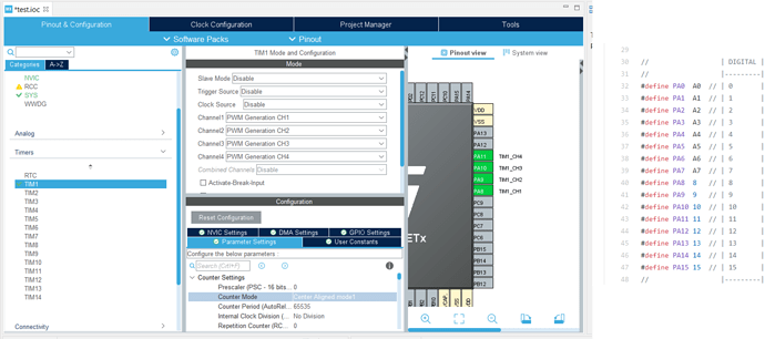
Also a small update for chosing the correct pins. I followed the steps from @Owen_Williams from the ā€œNUCLEO STM32F302R8 can not runā€ topic. (hopefully I did it correct). It shows that I need to use the following pins that use the same timer (using the Nucleo - F446RE):

I changed the pins and the code so that it has the following setup:

#define INH_A 8
#define INH_B 9
#define INH_C 10
#define EN_GATE 11
#define M_PWM 6
#define M_OC 5
#define OC_ADJ 7

But unfortunately it still will not work. It still starts with calibrating and then it gets stuck.

I am still using the following code for the PWM setup:

BLDCDriver3PWM driver = BLDCDriver3PWM(INH_A, INH_B, INH_C, EN_GATE);

Instead of:

BLDCDriver3PWM driver = BLDCDriver3PWM(PA8, PA9, PA10, PA11);

Because otherwise it will even not calibrateā€¦

Greetings,

Wittecactus

Hey @Wittecactus,

Iā€™ve checked the datasheet of your motor and it should have 24 poles, or 12 pole pairs.
Try running the:

BLDCMotor motor = BLDCMotor(12);

Very elegant leg design :smiley::+1:

Hey @Antun_Skuric,

With all the different codes I tried, I totally forgot to change that in this oneā€¦ I changed the pole pairs to 12!

The problem still remains, now sometimes with heavy vibration of the motor. Again added a video to the photo folder to show what happens.

Thank you so much for looking into my problem! :slight_smile:

Greetings,

Wittecactus

Hey @Wittecactus,
I know this is maybe a stupid question. But have you tried the open loop. Can you run the open-loop position control and see if the motor actually follows the position commands. Like if you set set the position 314 rad or -314 rad does it return back to the same location?

Hi @Antun_Skuric,

There are no stupid questions! I did try open loop velocity last time but did not do open loop position control. I made the following (working :slight_smile:) code tonight:

#include <SimpleFOC.h>

// DRV8302 pins connections
// don't forget to connect the common ground pin
#define   INH_A 8
#define   INH_B 9
#define   INH_C 10
#define   EN_GATE 11
#define   M_PWM 6 
#define   M_OC 5
#define   OC_ADJ 7

// motor instance
BLDCMotor motor = BLDCMotor(12);

// driver instance
BLDCDriver3PWM driver = BLDCDriver3PWM(INH_A, INH_B, INH_C, EN_GATE);

void setup() {

  // DRV8302 specific code
  // M_OC  - enable over-current protection
  pinMode(M_OC,OUTPUT);
  digitalWrite(M_OC,LOW);
  // M_PWM  - enable 3pwm mode
  pinMode(M_PWM,OUTPUT);
  digitalWrite(M_PWM,HIGH);
  // OD_ADJ - set the maximum over-current limit possible
  // Better option would be to use voltage divisor to set exact value
  pinMode(OC_ADJ,OUTPUT);
  digitalWrite(OC_ADJ,HIGH);

  // configure driver
  driver.voltage_power_supply = 10; //Using exernal power supply set on 10 volt with current limit set to 1 amps.
  driver.init();
  motor.linkDriver(&driver);
  
  // limiting motor movements
  motor.voltage_limit = 1;   // rad/s
  motor.velocity_limit = 5; // rad/s
  // open loop control config
  motor.controller = ControlType::angle_openloop;

  // init motor hardware
  motor.init();
  
  Serial.begin(115200);
  Serial.println("Motor ready!");
  _delay(1000);
}

float target_position = 0; // rad/s

void loop() {
  // open  loop angle movements 
  // using motor.voltage_limit and motor.velocity_limit

  
  motor.move(target_position);

  // receive the used commands from serial
  serialReceiveUserCommand();
}

// utility function enabling serial communication with the user to set the target values
// this function can be implemented in serialEvent function as well
void serialReceiveUserCommand() {
  
  // a string to hold incoming data
  static String received_chars;
  
  while (Serial.available()) {
    // get the new byte:
    char inChar = (char)Serial.read();
    // add it to the string buffer:
    received_chars += inChar;
    // end of user input
    if (inChar == '\n') {
      
      // change the motor target
      target_position = received_chars.toFloat();
      Serial.print("Target position: ");
      Serial.println(target_position);
      
      // reset the command buffer 
      received_chars = "";
    }
  }
}

The motor runs fairly smooth. Position control is fairly accurate: 2Pi rad is not exactly one turn in real life (sometimes 20 percent more or less). So this confirms that the Nucleo, driver and motor are correctly working together with the correct pins.

The sensor is also working.

But if those two things are combined to closed loop, then it acts weirdā€¦ Maybe something goes wrong with the linking?

Greetings,

Wittecactus

Hey @Wittecactus,

The motor should come to the same location each time. If it does not that means that it either skips steps (but that you would hear - loud skipping) or the number of pole pairs is wrong.

Please try varying the pole pair number until you get the ā€œperfectā€ position following. :smiley:

Hi @Antun_Skuric,

Thanks for the fast reply! :slight_smile:

I formulated myself wrong. I meant that if the motor goes to 30 rad and then back to 0 rad, then it is back in the exact same postition. But if you ask the motor to turn 2Pi, than it does not make a full turn, but if you go back to zero, than it is at the exact same location!

Greetings,

Wittecactus

The 2pi and 0 have to be exactly same location. This is the sign of wrong number of pole pairs.

Try finding the pole pair number that achieves that.

Found it! 11 pole pairs. I rechecked it online and there are indeed 22 poles. So 11 pole pairs is the number to make it turn exacty in the right way!

When this change is also made to the closed loop code, it still will not workā€¦ But we are certain of the pole pairs now :slight_smile:

I am running out of options :smiley:

So there are two that I can think of at the moment.

  1. Your magnet is not well fixed into the motor and it somehow misaligned. This you could test bt setting the target voltage to 0 and running the code. Your motor should not move at the beginning and you should be able to move it by hand slowly.
  2. Your magnet might be wrongly polarized, we had a theread already about a problem very similar to what you are showing here: Motor doesn't turn in FOC mode
  3. Something is wrong with the library code. But you have really the most standard setup we have here, if your setup does not work due to the library issue, it is a really sneaky one :smiley:
    Are you using the latest library release v2.0.2, that one is pretty well tested so far.
1 Like

Hi @Antun_Skuric,

You got to be kidding me :joy:. The magnets delivered with the sensor are axially magnetized instead of diametrically magnetized. I checked it with a compass. I am going to order the right magnets tonight and will update you when it is delivered after the weekend!

Thank you for helping me! And also helping me this fast. Really appreciated!

I hope that someday, I can also help people on the forum. If you or someone else needs help on the mechanical side of things, send me a message!

Greetings,

Wittecactus

This is a common learning experience! I think you are the third to discover their magnets are not diametric!

I seemed to remember someone managed to get simplefoc working by gluing a ā€˜normalā€™ magnet sideways. Probably not recommended :wink:

Hi all!

Great news: the magnets arrived early!

Bad new: The problem still persistsā€¦

I also changed the motor mount the sensor is further away from the motor, but that did not helpā€¦

I also swapped in a new sensor with the reasoning that the other is one is broken but that did not helpā€¦

If I try open loop, everything works fine. When trying closed loop and applying 0 volts, the sensor works correctly. But when those things are combined, it will not work. I tried the whole day, and two times, the motor worked properly, but after restarting the STM, then it did not work.

Do you have some other suggestions? Or maybe some things a beginner like me can do wrong?

Thank you again for helping me!

Greetings,

Wittecactus