Hi guys.
Hope you all doing well.
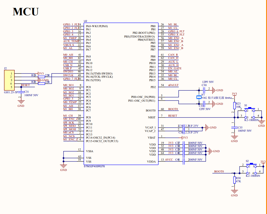
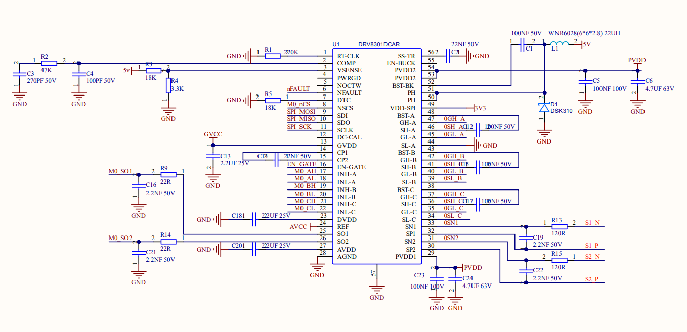
Recently Im working on motor control board using DRV8301 and STM32.
I have trouble with SPI.
My Fault pin indicates LOW(no fault) but SPI fault bit(bit 15) keep indicates 1(fault), with no data bits.
Any advice?
Heres my code, serial output and board sch.
Thank you.
#include "main.h"
#include "usb_device.h"

SPI_HandleTypeDef hspi3;

#define AS5047_CS_GPIO_Port GPIOA
#define AS5047_CS_Pin GPIO_PIN_15

#define DRV8301_CS_GPIO_Port GPIOC
#define DRV8301_CS_Pin       GPIO_PIN_13

uint16_t readAS5047_raw(void)
{
    uint8_t tx[2] = {0xFF, 0xFF};
    uint8_t rx_dummy[2] = {0};
    uint8_t rx_data[2]  = {0};

    HAL_GPIO_WritePin(AS5047_CS_GPIO_Port, AS5047_CS_Pin, GPIO_PIN_RESET);
    HAL_SPI_TransmitReceive(&hspi3, tx, rx_dummy, 2, HAL_MAX_DELAY);
    HAL_GPIO_WritePin(AS5047_CS_GPIO_Port, AS5047_CS_Pin, GPIO_PIN_SET);
    HAL_Delay(1);

    HAL_GPIO_WritePin(AS5047_CS_GPIO_Port, AS5047_CS_Pin, GPIO_PIN_RESET);
    HAL_SPI_TransmitReceive(&hspi3, tx, rx_data, 2, HAL_MAX_DELAY);
    HAL_GPIO_WritePin(AS5047_CS_GPIO_Port, AS5047_CS_Pin, GPIO_PIN_SET);

    return (rx_data[0] << 8) | rx_data[1];
}

uint8_t parity(uint16_t value)
{
    uint8_t count = 0;
    for (int i = 0; i < 15; i++) {
        count += (value >> i) & 0x01;
    }
    return count % 2;
}

uint16_t readAS5047_register(uint16_t addr)
{
    uint8_t tx[2], rx[2];
    uint16_t command = addr & 0x3FFF;
    command |= (parity(command) << 15);

    tx[0] = (command >> 8) & 0xFF;
    tx[1] = command & 0xFF;

    HAL_GPIO_WritePin(AS5047_CS_GPIO_Port, AS5047_CS_Pin, GPIO_PIN_RESET);
    HAL_SPI_TransmitReceive(&hspi3, tx, rx, 2, HAL_MAX_DELAY);
    HAL_GPIO_WritePin(AS5047_CS_GPIO_Port, AS5047_CS_Pin, GPIO_PIN_SET);
    HAL_Delay(1);

    tx[0] = 0xFF;
    tx[1] = 0xFF;

    HAL_GPIO_WritePin(AS5047_CS_GPIO_Port, AS5047_CS_Pin, GPIO_PIN_RESET);
    HAL_SPI_TransmitReceive(&hspi3, tx, rx, 2, HAL_MAX_DELAY);
    HAL_GPIO_WritePin(AS5047_CS_GPIO_Port, AS5047_CS_Pin, GPIO_PIN_SET);

    return (rx[0] << 8) | rx[1];
}

uint16_t drv8301_transfer(uint16_t txdata)
{
    uint8_t tx[2], rx[2];
    tx[0] = (txdata >> 8) & 0xFF;
    tx[1] = txdata & 0xFF;

    HAL_GPIO_WritePin(DRV8301_CS_GPIO_Port, DRV8301_CS_Pin, GPIO_PIN_RESET);
    HAL_Delay(10);
    HAL_SPI_TransmitReceive(&hspi3, tx, rx, 2, HAL_MAX_DELAY);
    HAL_Delay(10);
    HAL_GPIO_WritePin(DRV8301_CS_GPIO_Port, DRV8301_CS_Pin, GPIO_PIN_SET);

    return (rx[0] << 8) | rx[1];
}

uint16_t drv8301_read(uint8_t addr)
{
    uint16_t cmd = (1 << 15) | ((addr & 0x0F) << 11);
    drv8301_transfer(cmd);
    return drv8301_transfer(0x0000);
}

void drv8301_write(uint8_t addr, uint16_t data)
{
    uint16_t cmd = ((addr & 0x0F) << 11) | (data & 0x7FF);
    drv8301_transfer(cmd);
}

void drv_cr_setup()
{
  drv8301_write(0x02, 0x03D1);
  drv8301_write(0x03, 0x0000);
}

int main(void)
{
  HAL_Init();

  SystemClock_Config();

  MX_GPIO_Init();
  MX_SPI3_Init();
  MX_USB_DEVICE_Init();

  HAL_GPIO_WritePin(GPIOB, GPIO_PIN_12, GPIO_PIN_SET);
  HAL_Delay(500);

  HAL_GPIO_WritePin(GPIOB, GPIO_PIN_12, GPIO_PIN_RESET);
  HAL_Delay(10);
  HAL_GPIO_WritePin(GPIOB, GPIO_PIN_12, GPIO_PIN_SET);
  HAL_Delay(10);

  while (1)
  {
    uint16_t sr1 = drv8301_read(0x00);
    uint16_t sr2 = drv8301_read(0x01);
    uint16_t cr1 = drv8301_read(0x02);
    uint16_t cr2 = drv8301_read(0x03);

    char buf2[128];
    sprintf(buf2, "SR1=0x%04X, SR2=0x%04X, CR1=0x%04X, CR2=0x%04X\r\n", sr1, sr2, cr1, cr2);
    CDC_Transmit_FS((uint8_t*)buf2, (uint16_t)strlen(buf2));
    HAL_Delay(500);

    if (HAL_GPIO_ReadPin(GPIOD, GPIO_PIN_2) == GPIO_PIN_RESET) {
        CDC_Transmit_FS((uint8_t*)"FAULT\r\n", 7);
    } else {
        CDC_Transmit_FS((uint8_t*)"OK\r\n", 4);
    }
  }
}

void SystemClock_Config(void)
{
  RCC_OscInitTypeDef RCC_OscInitStruct = {0};
  RCC_ClkInitTypeDef RCC_ClkInitStruct = {0};

  __HAL_RCC_PWR_CLK_ENABLE();
  __HAL_PWR_VOLTAGESCALING_CONFIG(PWR_REGULATOR_VOLTAGE_SCALE1);

  RCC_OscInitStruct.OscillatorType = RCC_OSCILLATORTYPE_HSE;
  RCC_OscInitStruct.HSEState = RCC_HSE_ON;
  RCC_OscInitStruct.PLL.PLLState = RCC_PLL_ON;
  RCC_OscInitStruct.PLL.PLLSource = RCC_PLLSOURCE_HSE;
  RCC_OscInitStruct.PLL.PLLM = 4;
  RCC_OscInitStruct.PLL.PLLN = 144;
  RCC_OscInitStruct.PLL.PLLP = RCC_PLLP_DIV2;
  RCC_OscInitStruct.PLL.PLLQ = 6;
  if (HAL_RCC_OscConfig(&RCC_OscInitStruct) != HAL_OK)
  {
    Error_Handler();
  }

  RCC_ClkInitStruct.ClockType = RCC_CLOCKTYPE_HCLK|RCC_CLOCKTYPE_SYSCLK
                              |RCC_CLOCKTYPE_PCLK1|RCC_CLOCKTYPE_PCLK2;
  RCC_ClkInitStruct.SYSCLKSource = RCC_SYSCLKSOURCE_PLLCLK;
  RCC_ClkInitStruct.AHBCLKDivider = RCC_SYSCLK_DIV1;
  RCC_ClkInitStruct.APB1CLKDivider = RCC_HCLK_DIV4;
  RCC_ClkInitStruct.APB2CLKDivider = RCC_HCLK_DIV2;

  if (HAL_RCC_ClockConfig(&RCC_ClkInitStruct, FLASH_LATENCY_4) != HAL_OK)
  {
    Error_Handler();
  }
}

static void MX_SPI3_Init(void)
{
  hspi3.Instance = SPI3;
  hspi3.Init.Mode = SPI_MODE_MASTER;
  hspi3.Init.Direction = SPI_DIRECTION_2LINES;
  hspi3.Init.DataSize = SPI_DATASIZE_8BIT;
  hspi3.Init.CLKPolarity = SPI_POLARITY_LOW;
  hspi3.Init.CLKPhase = SPI_PHASE_2EDGE;
  hspi3.Init.NSS = SPI_NSS_SOFT;
  hspi3.Init.BaudRatePrescaler = SPI_BAUDRATEPRESCALER_64;
  hspi3.Init.FirstBit = SPI_FIRSTBIT_MSB;
  hspi3.Init.TIMode = SPI_TIMODE_DISABLE;
  hspi3.Init.CRCCalculation = SPI_CRCCALCULATION_DISABLE;
  hspi3.Init.CRCPolynomial = 10;
  if (HAL_SPI_Init(&hspi3) != HAL_OK)
  {
    Error_Handler();
  }
}

static void MX_GPIO_Init(void)
{
  GPIO_InitTypeDef GPIO_InitStruct = {0};

  __HAL_RCC_GPIOC_CLK_ENABLE();
  __HAL_RCC_GPIOH_CLK_ENABLE();
  __HAL_RCC_GPIOB_CLK_ENABLE();
  __HAL_RCC_GPIOA_CLK_ENABLE();
  __HAL_RCC_GPIOD_CLK_ENABLE();

  HAL_GPIO_WritePin(GPIOC, GPIO_PIN_13, GPIO_PIN_RESET);
  HAL_GPIO_WritePin(GPIOB, GPIO_PIN_12, GPIO_PIN_RESET);
  HAL_GPIO_WritePin(GPIOA, GPIO_PIN_15, GPIO_PIN_RESET);

  GPIO_InitStruct.Pin = GPIO_PIN_13;
  GPIO_InitStruct.Mode = GPIO_MODE_OUTPUT_PP;
  GPIO_InitStruct.Pull = GPIO_NOPULL;
  GPIO_InitStruct.Speed = GPIO_SPEED_FREQ_LOW;
  HAL_GPIO_Init(GPIOC, &GPIO_InitStruct);

  GPIO_InitStruct.Pin = GPIO_PIN_12;
  GPIO_InitStruct.Mode = GPIO_MODE_OUTPUT_PP;
  GPIO_InitStruct.Pull = GPIO_NOPULL;
  GPIO_InitStruct.Speed = GPIO_SPEED_FREQ_LOW;
  HAL_GPIO_Init(GPIOB, &GPIO_InitStruct);

  GPIO_InitStruct.Pin = GPIO_PIN_15;
  GPIO_InitStruct.Mode = GPIO_MODE_OUTPUT_PP;
  GPIO_InitStruct.Pull = GPIO_NOPULL;
  GPIO_InitStruct.Speed = GPIO_SPEED_FREQ_LOW;
  HAL_GPIO_Init(GPIOA, &GPIO_InitStruct);

  GPIO_InitStruct.Pin = GPIO_PIN_2;
  GPIO_InitStruct.Mode = GPIO_MODE_INPUT;
  GPIO_InitStruct.Pull = GPIO_NOPULL;
  HAL_GPIO_Init(GPIOD, &GPIO_InitStruct);
}

void Error_Handler(void)
{
  __disable_irq();
  while (1)
  {
  }
}

#ifdef USE_FULL_ASSERT
void assert_failed(uint8_t *file, uint32_t line)
{
}
#endif
SR1=0x8000, SR2=0x8800, CR1=0x9000, CR2=0x9800
OK
SR1=0x8000, SR2=0x8800, CR1=0x9000, CR2=0x9800
OK
SR1=0x8000, SR2=0x8800, CR1=0x9000, CR2=0x9800
OK
SR1=0x8000, SR2=0x8800, CR1=0x9000, CR2=0x9800
OK
SR1=0x8000, SR2=0x8800, CR1=0x9000, CR2=0x9800
OK
SR1=0x8000, SR2=0x8800, CR1=0x9000, CR2=0x9800
OK