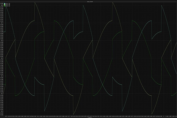
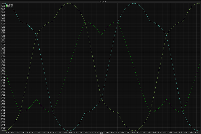
I think I should be able to test this pretty easily tonight, I’ll try to scope the voltage and see what it’s doing on the hardware. I didn’t write the state machine code, I wrote a version using fabs and fmin/fmax, and I didn’t have a scope when this initially got written.
Looks like you’re right! This doesn’t seem to do what we expected.
Here’s my initial implementation using fmin/fmax, this does match the paper and python sim.
and here’s the phase voltages.
Edit: Looking at this, now I’m not sure why the phase voltages go negative at some point. That shouldn’t happen.
Edit2: I think I should have used driver->voltage_limit or driver->voltage_power_supply to calculate V0, instead of the motor voltage limit. Motor voltage can go negative, as it’s centered around zero. Driver voltages cannot, they’re single sided.
Thank you very much for the investigation.
Edit: Looking at this, now I’m not sure why the phase voltages go negative at some point. That shouldn’t happen.
It could be the positions in the switch statements.
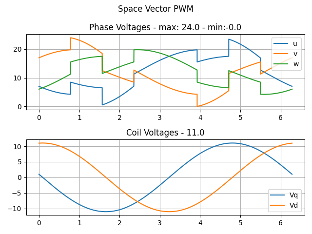
If I change the simulation input above (setting Ud=1 and subtract 1 from Uq)
	float Vs=24;
	driver->voltage_limit=Vs;
	float Uq=Vs/2-1;
	float Ud=1;
I get the following result in the simulation:
Edit2: I think I should have used driver->voltage_limit or driver->voltage_power_supply to calculate V0, instead of the motor voltage limit. Motor voltage can go negative, as it’s centered around zero. Driver voltages cannot, they’re single sided.
If you refer to my first picture: The reason for the negative PWM is that I made my own driver for an Arduino Uno with 8 bit PWM. Because I liked it more I gave my PWM-Block the input ranges for pwmA,pwmB,pwmC the values -128 .. 127 (int8_t).
Reason: float calculations take to much time on this MCUs.
I meant the values in the second image I posted, which are generated without any switch statements, just calls to min/max.
Yeah, that is strange. Probably you can not use the full amplitude. What happens, if you decrease the amplitude a little bit?
Hey guys!
This is an awesome discussion, I’m having so much fun reading through it.
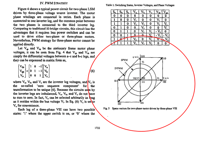
Thanks for the paper link, I was so happy to see the same graphs that I’ve discussed in the inital post ![]()
At least this confirms that my thinking was on a good track.
But as you made me realize, my idea that we could use just a standard BLDC commutation was wrong.
We cannot use the Clarke trasnform here because the phases are not 120degrees apart.
So we need to come up with our own transformation form u_\alpha and u_\beta to u_a,u_b and u_{mid}. For steppers, the voltages u_\alpha and u_\beta correspond exactly to their phase voltages.
So in theory, for any votlage vector we wanna set
u = \begin{bmatrix} u_\alpha \\ u_\beta \end{bmatrix}
we are absolutely free to chose any combination of u_a,u_b and u_{mid} that satisfies the following equations
u_\alpha = u_a - u_{mid}
and
u_\beta = u_b - u_{mid}
And the $u_{mid} can be chosen as we wish, as long as it’s in the limits of u_{mid}\in[0,U_{max}/\sqrt{2}]
That seems to explain how @Copper280z and @VIPQualityPost had still manage to get nice motor behavior even though their phase voltage they were setting to the motor was not what they intended to be. It was a different waveform, but it sill generated nice 90 degree-apart sinusoidal voltages on u_\alpha and u_\beta. And respected the equations above.
The good thing about the SVPWM proposed in the paper is that, as opposed to the sinusoidal modulation it is able achieve higher voltages u_\alpha and u_\beta within the limits u_a,u_b,u_{mid} \in [0,U_{max}].
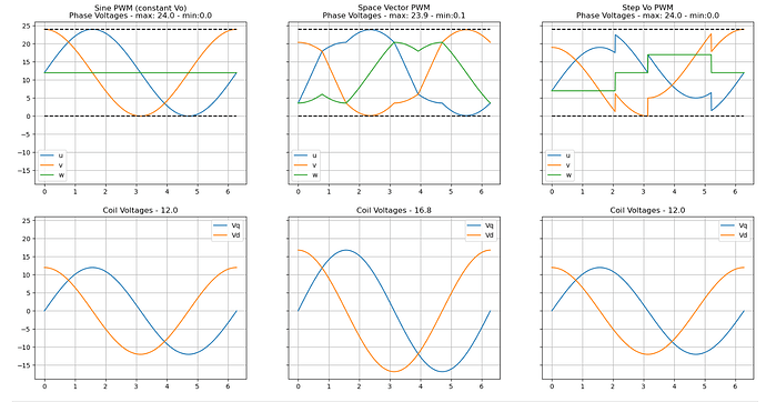
But for fun, I’ve taken your code and added another u_{mid} version, just to show that they all would result in the same sinusoidal waves on u_\alpha and u_\beta. But they would not be as efficient in exploiting the full range u_a,u_b,u_{mid} \in [0,U_{max}].
The code
from matplotlib import pyplot as plt
import numpy as np

theta = np.linspace(0, 2*np.pi, 1000)

Vs = 24

fig,axs  = plt.subplots(2,3, figsize=(20,10),sharey= True)

def constant_vo():

    Vo = Vs/2
    Vd = Vo*np.sin(theta)
    Vq = Vo*np.cos(theta)

    u = Vd + Vo
    v = Vq + Vo
    w = Vo * np.ones_like(theta)

    a = axs[0,0]
    a.set_title(f"Sine PWM (constant Vo)\nPhase Voltages - max: {np.max([u,v,w]):.1f} - min:{np.min([u,v,w]):.1f}")
    a.plot(theta, u)
    a.plot(theta, v)
    a.plot(theta, w)
    a.legend(['u', 'v', 'w'])
    a.plot(theta,np.ones_like(theta)*Vs,"--k")
    a.plot(theta,np.ones_like(theta)*0,"--k")
    a.grid()
    a = axs[1,0]
    a.set_title(f"Coil Voltages - {np.max([u-w,v-w]):.1f}")
    a.plot(theta, u-w)
    a.plot(theta, v-w)
    a.legend(['Vq', 'Vd'])
    a.grid()
    # a.tight_layout()


def space_vector():

    Vd = 0.7*Vs*(np.sin(theta))
    Vq = 0.7*Vs*(np.cos(theta))
    Vmin = np.min(np.asarray([Vd, Vq, np.zeros_like(theta)]), axis=0)
    Vmax = np.max(np.asarray([Vd, Vq, np.zeros_like(theta)]), axis=0)
    Vo = -(Vmin+Vmax)/2 + Vs/2

    u = Vd + Vo
    v = Vq + Vo
    w = Vo

    a = axs[0,1]
    a.set_title(f"Space Vector PWM\nPhase Voltages - max: {np.max([u,v,w]):.1f} - min:{np.min([u,v,w]):.1f}")
    a.plot(theta, u)
    a.plot(theta, v)
    a.plot(theta, w)
    a.legend(['u', 'v', 'w'])
    a.plot(theta,np.ones_like(theta)*Vs,"--k")
    a.plot(theta,np.ones_like(theta)*0,"--k")
    a.grid()
    a = axs[1,1]
    a.set_title(f"Coil Voltages - {np.max([u-w,v-w]):.1f}")
    a.plot(theta, u-w)
    a.plot(theta, v-w)
    a.legend(['Vq', 'Vd'])
    a.grid()
    # a.tight_layout()

def step_vo():

    Vd = Vs/2*(np.sin(theta))
    Vq = Vs/2*(np.cos(theta))
    Vo = Vs/2*np.ones_like(Vd)
    Vo[:330] -= 5
    Vo[500:830] += 5

    u = Vd + Vo
    v = Vq + Vo
    w = Vo


    a = axs[0,2]
    a.set_title(f"Step Vo PWM\nPhase Voltages - max: {np.max([u,v,w]):.1f} - min:{np.min([u,v,w]):.1f}")
    a.plot(theta, u)
    a.plot(theta, v)
    a.plot(theta, w)
    a.legend(['u', 'v', 'w'])
    a.grid()
    a.plot(theta,np.ones_like(theta)*Vs,"--k")
    a.plot(theta,np.ones_like(theta)*0,"--k")
    a = axs[1,2]
    a.set_title(f"Coil Voltages - {np.max([u-w,v-w]):.1f}")
    a.plot(theta, u-w)
    a.plot(theta, v-w)
    a.legend(['Vq', 'Vd'])
    a.grid()
    # a.tight_layout()

constant_vo()
space_vector()
step_vo()
I would actually love to include this HybridStepper to the main library. I think that it would be a very nice addition to the existing code and it would make using steppers with the SimpleFOC much much easier. What do you guys think?
Are there some obvious drawbacks of integrating this to the main library?
If you feel that it’s ready then this would be very cool ![]() the first component to “graduate” to the main library…
the first component to “graduate” to the main library…
I think the only drawback is that then proper documentation needs to be created for it, and this may potentially be a source of confusion for users…
Perhaps it would be good to get the 2.3.4 release finished first and then include this in the next release, giving us time to create the docs for it?
we are absolutely free to chose any combination of ua,ub and umid that satisfies the following equations
uα=ua−umid
and
uβ=ub−umid
When you look at the first investigation I posted it could be seen that the difference of this erroneous jump SVM signals was a clean sine. Usually in industrial electronic designs jumps in signals are avoided because the cause high frequencies and lead to EMC problems. I’m not sure if this counts here because the underlying modulation is PWM witch has anyway fast rising edges but my feeling says the jumping waveforms should be avoided.
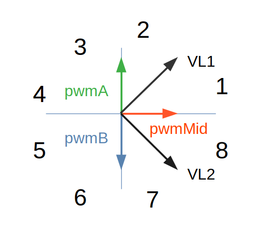
The sine wave modulation scheme I posted above
3 phase BLDC signals
pwmA=cos(phase);
pwmMid=sin(phase);
pwmB=-cos(phase);
results also in 70% voltage amplitude so at least for a FOC operation point where Ud=0 the SVM shown modulation brings no advantage.
I think it would be very useful to have it integrated. The reason why I use a 3 phase driver for a two phase stepper motor is simply because I have some Simple-Foc shields lying around here and I don’t have appropriate stepper motor drivers where I can create arbitrary waveforms.
For industrial applications it could be also relevant because you need only 3 half bridges instead of four and for many applications you can drive the motor anyway not higher then 70% PWM. In this cases some hardware costs could be probably saved.
I’m not sure that its ready yet ![]()
But I really like its potential and I feel confident that we can bring it to the sufficiently robust state. Also, with not that many changes to the library.
I agree, we already lack proper docs for stepper motors, so integrating this would require both more substantial effort in docs and being a bit more careful in explaining the differences.
Yes, I agree with this. We should roll out the next release without this change, and make a strategy to add it to the next one.
I agree. Also even though there are a lot of mid/high power BLDC drivers, there arent many stepper drivers. So this could enable using larger stepper motors with BLDC drivers, for example you could use B-G431B-ESC1 to drive nema23 or even nema32. ![]()
And the trade-off would be that you might not have the same amount of power as with a quad half-bridge stepper driver. But you can always increase the power-supply voltage and get more velocity/power range.
This ends up with a phase offset of something like pi/12, which means there needs to be 2 unique sin/cos/sincos calls per update. Otherwise it looks like this does perform similarly to the paper we originally tried to follow.
Those are 90 degrees apart, not 120, though? Each phase vector has equal magnitude, that doesn’t happen at any point in the proposed waveform.
For a two phase stepper motor the two phases have to be 90° apart. That is different to a three phase motor.
Each phase vector has equal magnitude, that doesn’t happen at any point in the proposed waveform.
I’m not sure that I understand what you mean. For normal operation of a two phase stepper motor you need a sine and a cosine signal for the two phases. When you use a three phase BLDC driver and you are using one phase as the middle signal and one terminal as phase A and the other as phase B the difference between phase A and the middle signal shall give a sine and the other a 90° phase shifted sine. This is shown in the Slide. With this signals you drive a stepper motor with ~70% of a normal stepper motor driver.
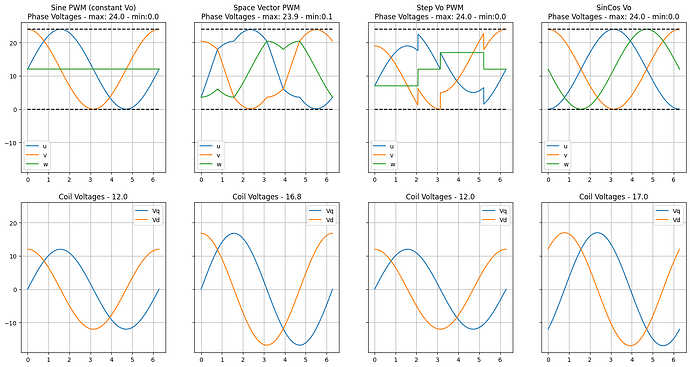
I do agree with that. I’ve added your modulation to the script as well.
Here is the script, so we can add more if someone has one to suggest ![]()
The one on the right is yours @ChrisMicro.
I’ve implemented it like this in the script (opposite signs than the one you wrote up) to get the same waverforms.
 u = Vs/2 + Vs/2*(-np.cos(theta))
 v = Vs/2 + Vs/2*(np.cos(theta))
 w = Vs/2 + Vs/2*(-np.sin(theta))
EDIT: Now by looking at it a bit more carefully, its not exaclty the same waveform. It’s shifted by some degrees.
Thank you ![]()
EDIT: Now by looking at it a bit more carefully, its not exaclty the same waveform. It’s shifted by some degrees.
I think the shift should be
thetaNew=theta-2*pi/8
Yes (Signals)
Each phase vector has equal magnitude, that doesn’t happen at any point in the proposed waveform.
They have, as you can see in the Graph.
Edit: It took me a bit, but I get it now, thanks!
Running high(er) power Nemas with a B-G431B-ESC1 is exactly my use-case and i would love to experiment with it.
Did anyone pick this up after v.2.3.4? Couldn’t find a branch or commits in dev ![]()
This was PEBCAK from my end, sorry!
For anyone else looking it is merged to Arduino-FOC-drivers . Thanks for the awesome addition ![]()
