Driving two-phase (bilpolar) steppers with three-phase (BLDC) driver - Hybrid stepper motor

Hi guys,

Few days ago I’ve read on the forum that there are some people as @VIPQualityPost and @Copper280z which used bipolar stepper motors as regular BLDC motors by connecting two of their wires together as one phase of the BLDC motor. This seems like such an creative and awesome idea. So as I was not actually sure about the implications of it, I’m starting this thread to discuss about it.

Some background

Bipolar stepper motors have two phases that are completely independent. Each of them has their own phase resistance.
Untitled Diagram.drawio (37)
Usually we drive them with two independent full bridge circuits. Full bridge drivers basically means that we can set both positive and negative voltages.

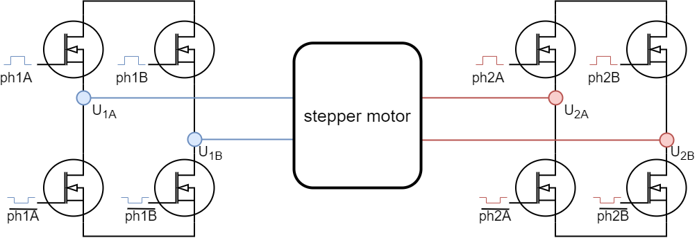
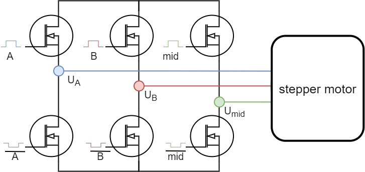
Having two full bridge circuits requires having four half-bridge drivers which is often hard to find, the BLDC drivers with three half-bridge circuits are much more common. So the question is ehat does happen if we connect two wires of a stepper together
Untitled Diagram.drawio (39)
and when we driver it with a BLDC driver.

Some ideas on the phase resistance

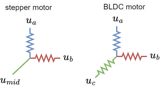
Stepper motor with two phases connected can be represented as a resistive load
Untitled Diagram.drawio (41)

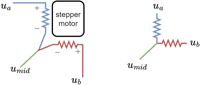
And what is visible right away is that it is not as a regular BLDC motor which has one equivalent phase resistance per phase. The stepper is unbalanced in terms of phase resistances.
Untitled Diagram.drawio (42)

For example, if the resistance of the stepper is R Ohms. Then the resitance between u_a and u_{mid} is R as well as between u_b and u_{mid}. However between u_a and u_b is 2R.
In a regular BLDC motor all these resistances would be equal to 2R.

I am not exactly sure how big of an influence this causes. I think that this could potentially create some vibrations due to the difference in the current/torque magnitude, due to the unbalanced resistance. But they might be small.
My intuition is also, if we control the stepper in current control mode, we should still be able to control its torque well, but I am not sure.

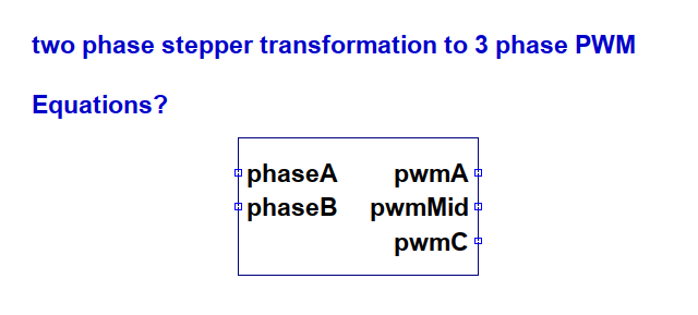
Some ideas on the phase voltage limits

Regular stepper

Untitled Diagram.drawio (37)
A regular stepper motor, driven with two full bridges which can produce any phase voltage between -U_{max} and U_{max}, where the U_{max} is usually the power supply voltage can be used to set any phase voltage vector which can be achieved by conbining the u_a and u_b phases.

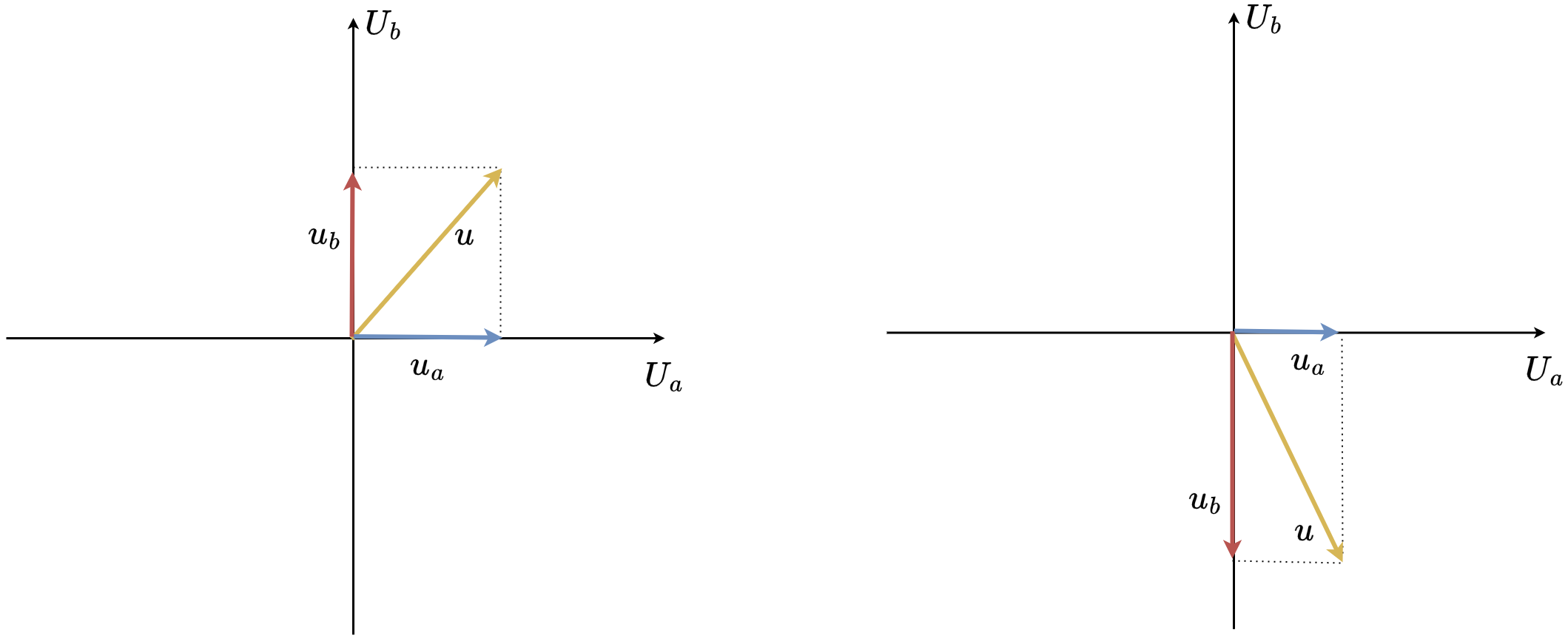
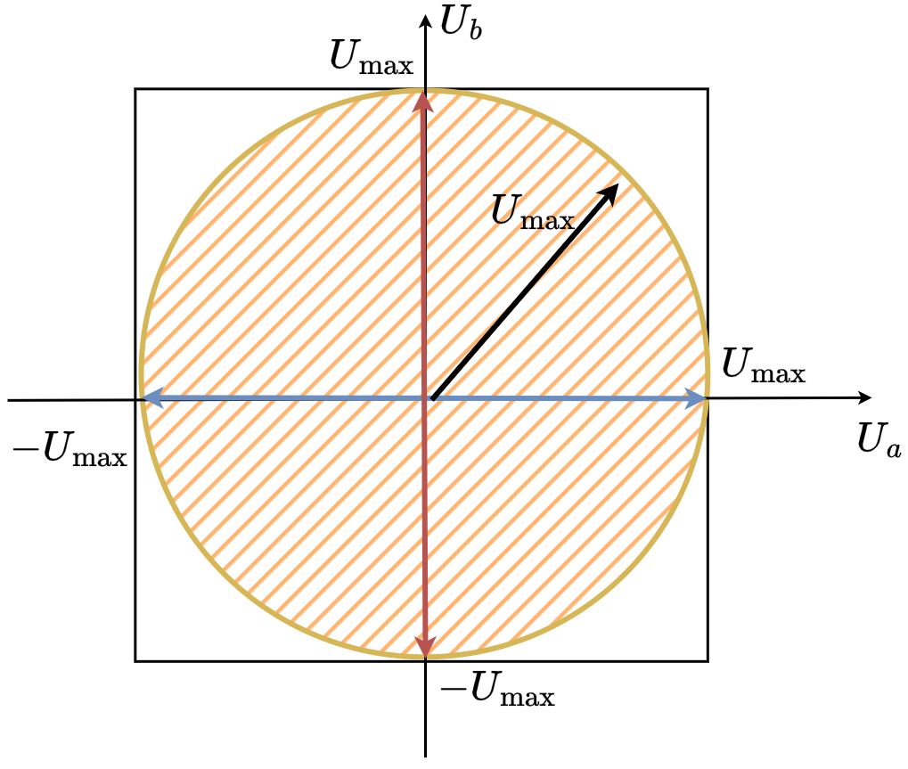
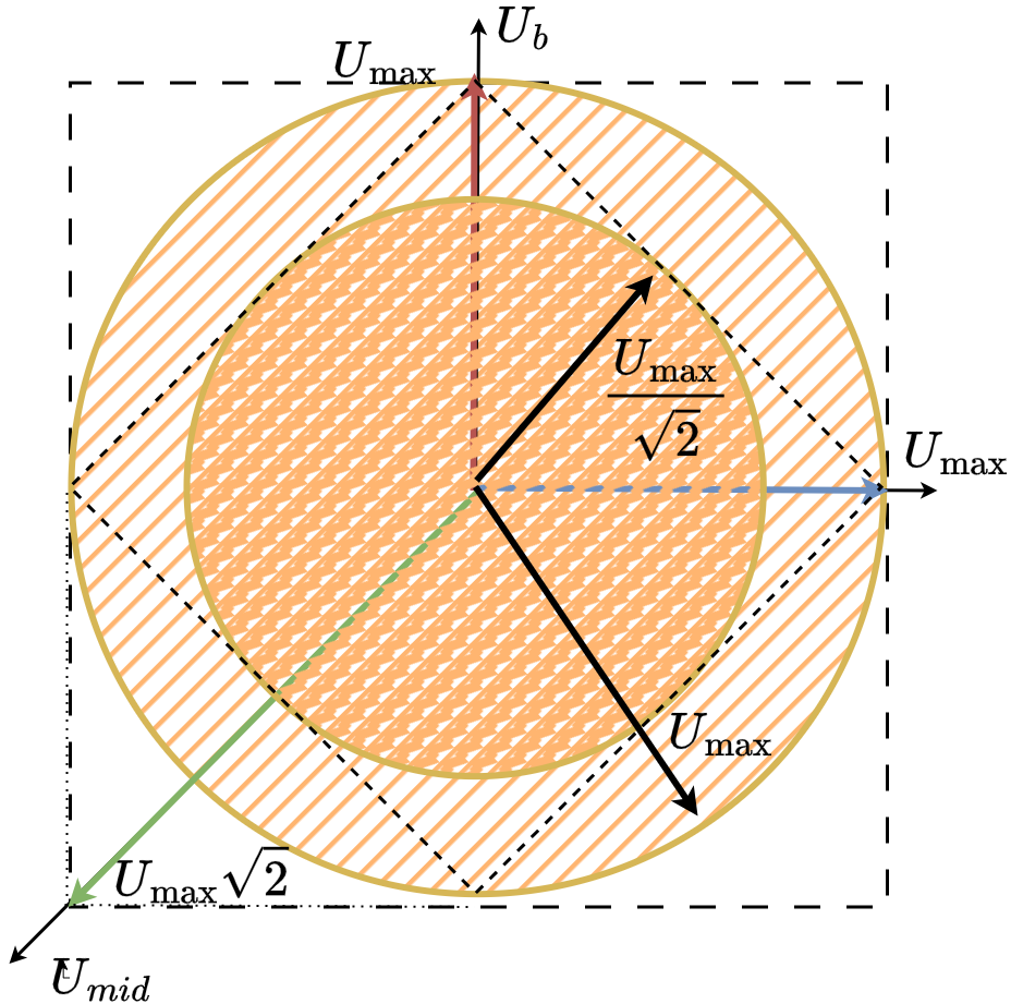
As both u_a and u_b are limited wiht U_{max} the set of all the posible phase voltage vectors can be described by the square:


As in SimpleFOC we want to be able to guarantee that we can achieve any vector magnitude with any orientation in space (electrical angle) we limit the voltage vector magnitude to the U_{max} and we sacrifice some parts of the possible vectors.

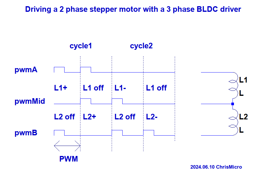
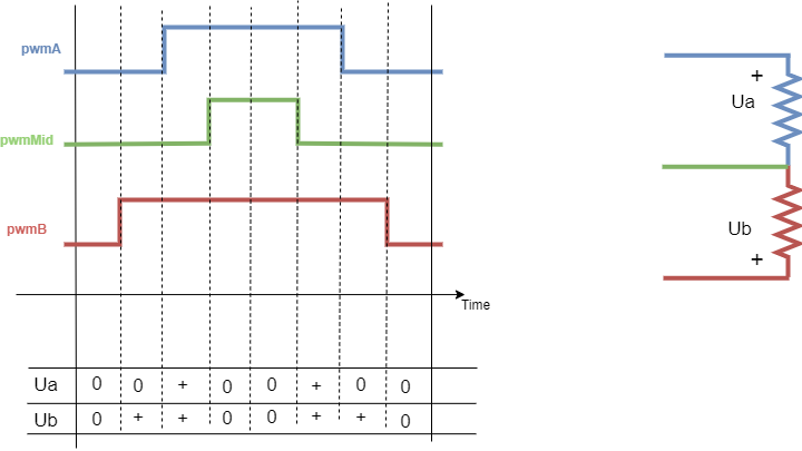
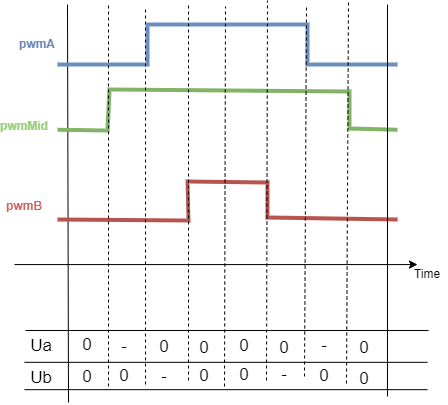
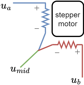
Stepper with connected phases

Untitled Diagram.drawio (39)
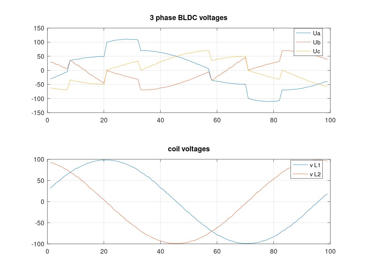
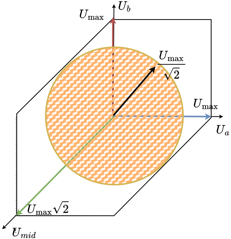
When we connect two phases of a stepper together we effectively obtain three unipolar (only positive) voltage vectors u_a, u_b and u_{mid}. These vectors can be visualised in space like this


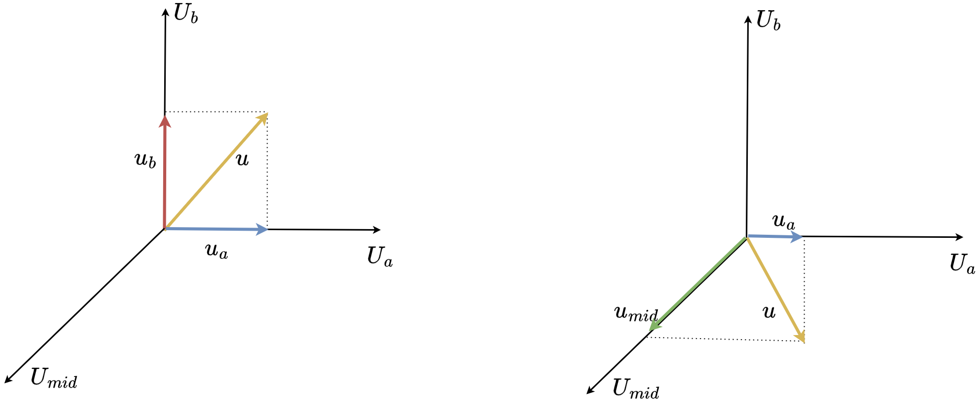
The vectors u_a and u_b are the same vectors as for the regular stepper but unipolar. They hare 90 degrees apart. While the vector u_{mid} is also unipolar, however 135 degrees from u_a and u_b.

They still can create a rotating voltage vector, they can apply a voltage vector in any direction in space (any electric angle). However in this configuration it can no longer cover the whole square as shown for regular stepper motors


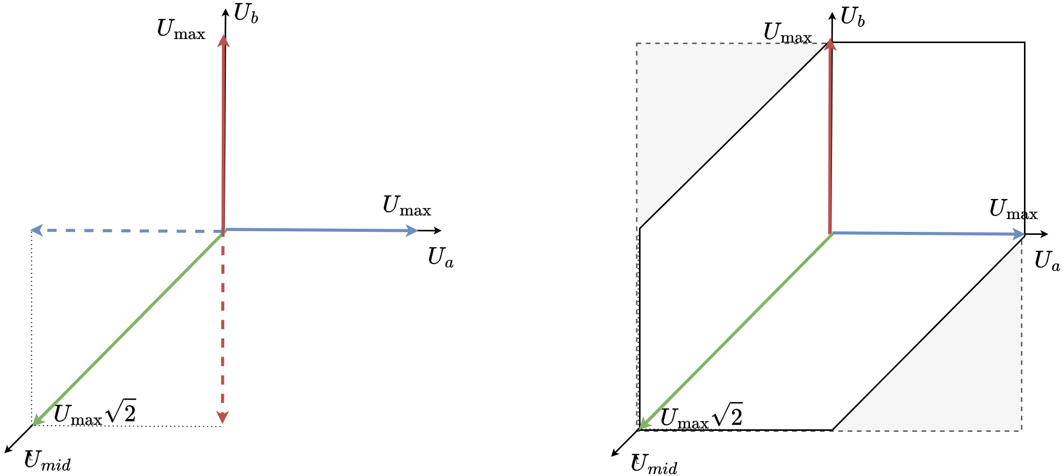
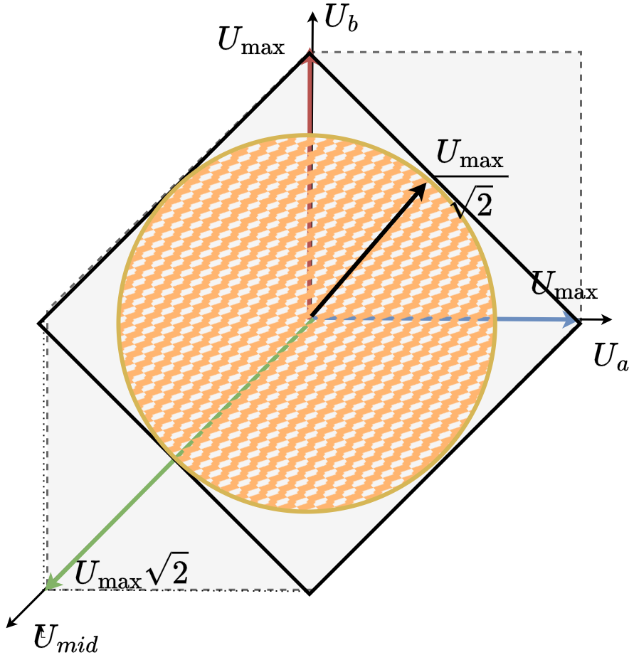
Instead of the square, the space of all the reachable voltage vectors is this elongated hexagon.
So in order to be able to find the maximum voltage vector magnitude that we can generate in any direction in space (electrical ablge) we need to once again fit a the lagest circle possible in this hexagon.

How do we get to U_{max}/\sqrt{2}

If we imagine a line between u_a =U_{max} and u_b=U_{max}, the circle will be touching it, as it touches the same line on the left side (line between u_a =-U_{max} and u_b=U_{max}).


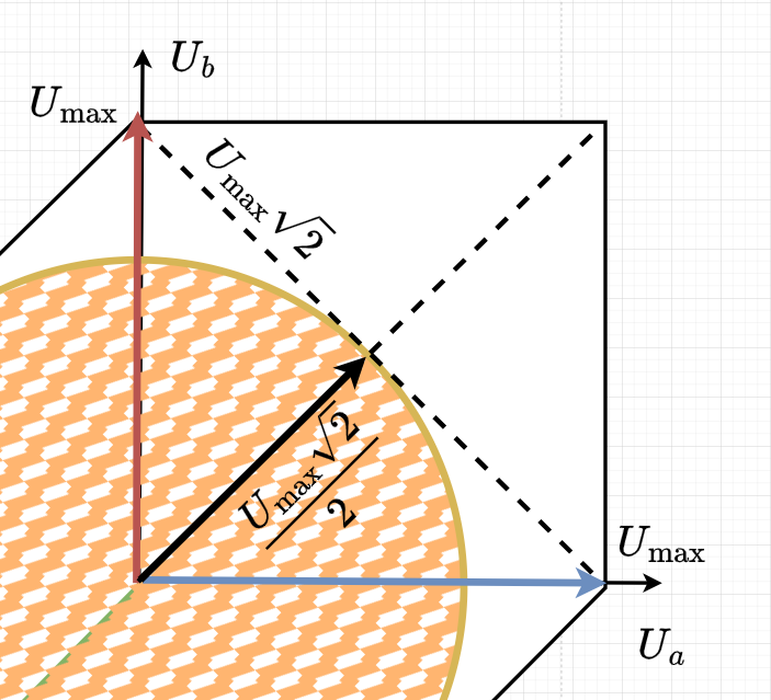
This line’s length can be calculated as U_{max}\sqrt{2} as a diagonal of the square with the side lenth U_{max}. Now as our circle touches this line in the middle, we know the the opposite diagonal going from u_a=u_b=0 to u_a=u_b=U_{max} has the same length and that the circle tourhes is in the middle as well. So the radius of the circle must be U_{max}\sqrt{2}/2 which can be simplified to U_{max}/\sqrt{2} .

So this new stepper configuration can be effectively seen as a stepper with the power supply voltage equal to the U_{max}/\sqrt{2}.

So when we put them side by side we get something like this

Some of my takeaways of my reflection

So if we set the maximum phase voltage (motor.voltage_limt) to U_{max}/\sqrt{2} we could use the regular BLDC driver (BLDCDriver3PWM) with the SimpleFOC and control this motor as any other BLDC motor.
At least in terms of the ability to apply any voltage vectro in any direction in space, this is perfectly enough.

But I do have some questions:

  • As the phase resistance is not uniform I am not sure how constant the torque/current produced by the constant phase magnitude vectors is.
  • Also what happens when we introduce the current control, do these torque imbalances disappear?
  • Maybe these effects are not even noticeable.

I’d be happy to hear what do you guys think.
Cheers,
Antun

1 Like

I think it is important that the PWM is divided in two cycles. In the first cycle coil L1 is driven and in the second cycle coil L2 is driven. I don’t know if the standard 3 phase PWM in SimpleFoc is matching this requirements.

Wow interesting point. In that way you would try to keep the independece.
That would be complicated to do with the current library implementation, at leas this muti-cycle approach.

Is this first pwmB in the first cycle intended to be low?

The center aligned-pwm might do something similar though. For example

Or for some other PWM duty cycles
Untitled Diagram.drawio (56)

It’s not exactly what you argued, as there are still some cases when they are both on at the same time (both Ua and Ub). But I’m not sure if that’s actually bad.

You are right, it has to be low. My first drawing was that the lowest line is the pwmMid and I forgot to correct it when using the middle line as pwmMid.
It might be that my modulation scheme could be optimized somehow because VIPQualityPost mentioned that he could achieve 70% power of a normal 2 phase driver. In my case because one phase can be active only half the time it is probably less.

This is actually something that I’d expect as is kinda corresponds to the U_{max}/\sqrt{2} which is \approx0.707U_{max}.

It’s true yeah. Huh its not trivial, I did not see it right away, but it makes sesne.

It is really an interesting question if the centred PWM has to be changed for that kind of application. I don’t know, probably some of the other readers might come up with good ideas. I have the strong feeling that the looking at the PWM signal level is necessary to tackle this problem and looking on the mean values is not enough.

Therefore the open questions are:

  • Has the modulation scheme to be altered from centred PWM or has the PWM edge mode to be used?
  • What are the equations to translate the two phases to 3 PWM signals? (for the PWM edge mode it would be somehow simple)
    twoPhaseStepper3PwmSymbol

Probably the solution is simpler than thought:

  • use centred PWM
  • set pwmMid to 50%
  • pwmA=phaseA[%]+50%
  • pwmB=phaseB[%]+50%

Yeah, but this only gives you only a part of the maximum voltage vector you can apply is bound within the square with a side of U_{max} (as opposed to the normal stepper which is bound to the square with a side length of 2U_{max}.

And when you compare the three approaches you get something like this:

The approach where you use only 0.5U_{max} per phase is equivalent a stepper with the half of the power supply voltage.

I am not sure what the best modulation is. However if we look at this problem from the point of view of the FOC control. We need to look at the voltage vectors rather than the phase voltages.

So for example if we wanna set a voltage vector u which is a combination of the phase voltages u_a and u_b

As we have three phases now u_a, u_b and u_{mid} we have infinitely many ways to set this voltage, using any combination of the these vectors that’s inside their limits.For example here are two different voltages u_a, u_b and u_{mid} which achieve the same voltage vector at the end.

But how to choose among all these modulations, that is the question! :smiley:

1 Like

I haven’t had a chance to read everything here, but I wanted to say that we didn’t drive the stepper motor with the unmodified BLDC code, we wrote a new modulation mode that drives the stepper with a perfect sine wave, but using 3 phases. We used a SVPWM method which allows driving up to 70% of Vbus.

This doesn’t introduce any extra vibration or anything, functionally it’s identical to driving it using the normal spwm stepper code.

I’ll have some time to read everything later and maybe try to find the paper we used to develop it initially, along with my quick python sim of the svpwm, showing that it is in fact a perfect sine wave.

I assume you guys have read through the code we PR’d into the drivers library? I’m the reason for the warning that got included, I think it was an overvoltage from inertia and fast decels that killed the bg431esc.

The same thing I described in the equations above but didn’t use SVPWM. For sine wave signals the result will be perfectly sine waves on both phases but I have the feeling clamping the mid phase to 50% and using SVPWM will introduce some disturbances because SVPWM is made for 3 phases.
Antun might be right and driving the 3 PWMs with other signals could give smoother results.

After a while of thinking, this should be the solution:

Read the next case in that switch statement, the one labeled “FOCModulationType::SpaceVectorPWM”. :slightly_smiling_face:

Read the next case in that switch statement, the one labeled “FOCModulationType::SpaceVectorPWM”. :slightly_smiling_face:

Tank you for the response. Do you mean this part ?
case FOCModulationType::SpaceVectorPWM:

I analysed the signals a little bit. The resulting waveform looks OK, but there are quite a view jumps in the signals.
Therefore the question is: does it have some advantages?

Edit: Here’s the paper: https://core.ac.uk/download/pdf/225191452.pdf

I think you need to change how you’re simulating the terminal voltages, that doesn’t look right, those can also never go negative.

image

Here’s the python I used to simulate this:

from matplotlib import pyplot as plt
import numpy as np

theta = np.linspace(0, 2*np.pi, 1000)

Vs = 24


def constant_vo():

    Vo = 24/2
    Vd = Vo*np.sin(theta)
    Vq = Vo*np.cos(theta)

    u = Vd + Vo
    v = Vq + Vo
    w = Vo * np.ones_like(theta)

    plt.subplot(211)
    plt.suptitle("Constant Vo")
    plt.title("Phase Voltages")
    plt.plot(theta, u)
    plt.plot(theta, v)
    plt.plot(theta, w)
    plt.legend(['u', 'v', 'w'])
    plt.subplot(212)
    plt.title("Coil Voltages")
    plt.plot(theta, u-w)
    plt.plot(theta, v-w)
    plt.legend(['Vq', 'Vd'])
    plt.tight_layout()
    plt.show()


def space_vector():

    Vd = 0.7*Vs*(np.sin(theta))
    Vq = 0.7*Vs*(np.cos(theta))
    Vmin = np.min(np.asarray([Vd, Vq, np.zeros_like(theta)]), axis=0)
    Vmax = np.max(np.asarray([Vd, Vq, np.zeros_like(theta)]), axis=0)
    Vo = -(Vmin+Vmax)/2 + Vs/2

    u = Vd + Vo
    v = Vq + Vo
    w = Vo

    plt.subplot(211)
    plt.suptitle("Space Vector PWM")
    plt.title(
        f"Phase Voltages - max: {np.max([u,v,w]):.1f} - min:{np.min([u,v,w]):.1f}")
    plt.plot(theta, u)
    plt.plot(theta, v)
    plt.plot(theta, w)
    plt.legend(['u', 'v', 'w'])
    plt.subplot(212)
    plt.title(f"Coil Voltages - {np.max([u-w,v-w]):.1f}")
    plt.plot(theta, u-w)
    plt.plot(theta, v-w)
    plt.legend(['Vq', 'Vd'])
    plt.tight_layout()
    plt.show()


constant_vo()
space_vector()

When considering current control, I think you need to change things, as you can treat the current in each independent leg as the alpha or beta current (which I incorrectly labeled as D and Q in the above chart/python), and ignore the shared leg entirely. I’m not sure exactly what happens if you pretend this arrangement is a standard BLDC motor, that might make for weird torque ripple, but I haven’t thought about it at all.

3 Likes

Very cool :slight_smile: Thank you very much for the paper and especially for the python simulation.

I implemented your SVM-C-code offline to run it on a PC. If I’m doing it right, there seems to be a difference between the python output and the microcontroller implementation. Did you check the signals with an oscilloscope?
SVM_dynamicCodeCheck1

Here is the cpp-code:

/*
 Offline calculation check for

 Arduino-FOC-drivers/src/motors/HybridStepperMotor/HybridStepperMotor.cpp

 to check signal correctness.

 Discussion:
 https://community.simplefoc.com/t/driving-two-phase-bilpolar-steppers-with-three-phase-bldc-driver-hybrid-stepper-motor/5043

 What:
 Offline calculation for the space vector modulation of a two phase stepper motor connected to a three phase BLDC driver.

 Why:
 This is a dynamic code check. It can be used to simulate the calculations of the microcontroller on a PC.

 How:
 The signal generation part of the space vector calculation was extracted from the microcontroller code
 and put in this cpp-file.

 1. Compile the cpp-code with e.g. Eclipse
 2. Run it on a PC to generate a log file
 2. Run the python script to visualize the result
    python showLog.py

 2024-06-13 ChrisMicro

 */
#include <stdint.h>
#include <stdio.h>
#include <string.h>
#include <math.h>

FILE *DataLoggerFile;
char Filename_logFile[2048];

typedef struct Driver{
  float voltage_limit=10;
}Driver;

Driver dr;
Driver *driver;

float _sin(float x)
{
	return sin(x);
}
float _cos(float x)
{
	return cos(x);
}

#define _PI 3.1415

float Ua,Ub,Uc;
/*
 code extracted from here:
 https://github.com/simplefoc/Arduino-FOC-drivers/blob/bfd07bd17eadcdae43ba0a85d74fe07ed04e26fc/src/motors/HybridStepperMotor/HybridStepperMotor.cpp#L422
*/

void setPhaseVoltage(float Uq, float Ud, float angle_el)
{
   //	angle_el = _normalizeAngle(angle_el);
   float _ca = _cos(angle_el);
   float _sa = _sin(angle_el);
   float center;
    // C phase moves in order to increase max bias on coils
    uint8_t sector = floor(4.0f * angle_el / _PI) + 1;
    Ua = (_ca * Ud) - (_sa * Uq);
    Ub = (_sa * Ud) + (_ca * Uq);

    // Determine max/ min of [Ua, Ub, 0] based on phase angle.
    switch (sector)
    {
    case 1:
    case 8:
      center = (driver->voltage_limit - Ua - Ub) / 2;
      break;

    case 2:
      center = (driver->voltage_limit - Ua - 0) / 2;
      break;

    case 3:
      center = (driver->voltage_limit - Ub - 0) / 2;
      break;

    case 4:
    case 5:
      center = (driver->voltage_limit - Ub - Ua) / 2;
      break;

    case 6:
      center = (driver->voltage_limit - 0 - Ua) / 2;
      break;

    case 7:
      center = (driver->voltage_limit - 0 - Ub) / 2;
      break;

    default: // this case does not occur, but compilers complain about uninitialized variables
      center = (driver->voltage_limit - 0) / 2;
      break;
    }

    Ua += center;
    Ub += center;
    Uc = center;

  //driver->setPwm(Ua, Ub, Uc);
}

int main(int argc, char **argv)
{
	driver=&dr;
	strcpy(Filename_logFile, "log.csv");
	DataLoggerFile=fopen(Filename_logFile, "w");

	printf("space vector calculation check ");

	float Vs=24;
    driver->voltage_limit=Vs;
	float Uq=Vs/2;
	float Ud=0;

	int numSteps=200;
	float theta=0;

	float angleDelta=2*_PI/numSteps;

	for(int n=0;n<numSteps;n++)
	{
		setPhaseVoltage(Uq, Ud, theta);
		theta+=angleDelta;
		fprintf(DataLoggerFile, "%f, %f, %f, %f\n",theta,Ua,Ub,Uc);
	}

	fclose(DataLoggerFile);
	printf("file %s written, program stopped",Filename_logFile);
	return 0;
}

And here is the python script to show the data:

#!/usr/bin/env python3

import numpy as np
import matplotlib.pyplot as plt

from numpy import genfromtxt

data = genfromtxt('log.csv', delimiter=',')

#print(data)

theta=data[:,0]        
u= data[:,1]
v= data[:,2]
w= data[:,3]

plt.subplot(211)
plt.suptitle("Space Vector PWM")
plt.title( f"Phase Voltages - max: {np.max([u,v,w]):.1f} - min:{np.min([u,v,w]):.1f}")
plt.plot(theta, u)
plt.plot(theta, v)
plt.plot(theta, w)
plt.grid()
plt.legend(['u', 'v', 'w'])

plt.subplot(212)
plt.title(f"Coil Voltages - {np.max([u-w,v-w]):.1f}")
plt.plot(theta, u-w)
plt.plot(theta, v-w)
plt.legend(['Vq', 'Vd'])
plt.tight_layout()

plt.grid()
plt.show()

When we were writing the feature, I definitely checked it on a scope and saw something that should have been close to the simulation. I thought that I had a notebook with the graphs using the switch statements, but seems that I have lost it… but the way the switch statement works is just looking at one period and manually choosing the center ( as I am sure you saw).

Hmm, in your online calculator it looks right but there might be a difference in the controller implementation. Because I copied exactly the the code of Copper280z (as you can see in my C-implementation)I think there should be an error.