Thank you very much for the investigation.
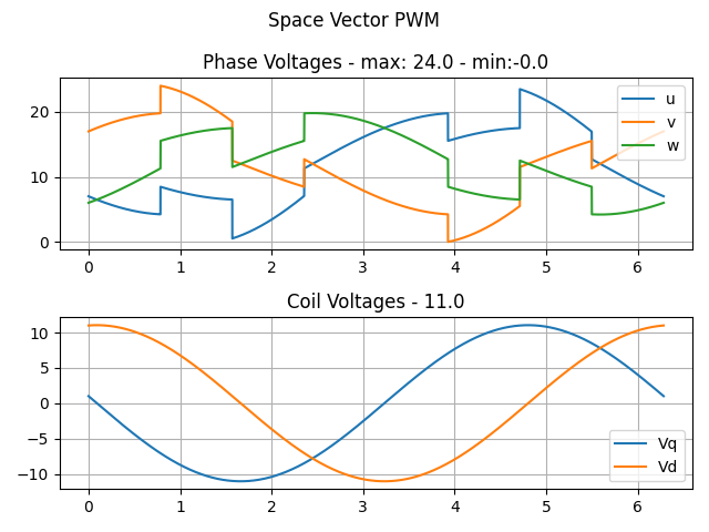
Edit: Looking at this, now I’m not sure why the phase voltages go negative at some point. That shouldn’t happen.
It could be the positions in the switch statements.
If I change the simulation input above (setting Ud=1 and subtract 1 from Uq)
	float Vs=24;
	driver->voltage_limit=Vs;
	float Uq=Vs/2-1;
	float Ud=1;
I get the following result in the simulation:
Edit2: I think I should have used driver->voltage_limit or driver->voltage_power_supply to calculate V0, instead of the motor voltage limit. Motor voltage can go negative, as it’s centered around zero. Driver voltages cannot, they’re single sided.
If you refer to my first picture: The reason for the negative PWM is that I made my own driver for an Arduino Uno with 8 bit PWM. Because I liked it more I gave my PWM-Block the input ranges for pwmA,pwmB,pwmC the values -128 .. 127 (int8_t).
Reason: float calculations take to much time on this MCUs.