Driving a 2.5ohm resistance 40.000 RPM BLDC motor

Hi!

I got a small 3 wire BLDC motor (no Hall sensor) from an auction from used dental parts. Specifically it’s a Dental Electric Brushless Micromotor.

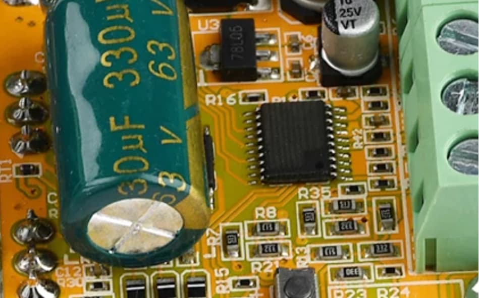
I bought just the motor and cable. But I have another one complete set just like it working and installed. (Driver, supply and micromotor)

I’d like to know it with FOC hardware/software, I could get it this extra motor I bought running back running again, by creating a new driver for it. I know I could search for an used original driver, but for the fun of the project, I’d like to create a new driver for it myself. I’ll use it as small driller for my hobby projects.

What I know about it is:

The BLDC motor itself have 5cm length, 2 cm diameter

The power supply for the original driver is 48V DC, 1.25A (50W-63W). So I guess the motor runs at max 48V DC, but not sure about it. Could be less. Is there a way to measure it? I could measure it in my other working unit, but just don’t know where in the PCB (or motor) to measure it.

The motor itself has 2.5 ohms of resistance between each two poles, so it sits between the gimbal motors and high power BLDC motors. It seems to have a max torque allowed in it’s original driver/supply of 3N.cm

Calculating the max current would give 19.2A (48V/2.5), which I think it’s too much… Is there a way to measure it also? I could measure in the other working unit if needed.

It runs at 40.000RPM max direct drive, with no gears.

It doesn’t have hall sensor wires, nor encoders. But It’s original controller can make it reverse rotation if needed.

I don’t need to know the position of the motor, nor the perfect exact speed. It’s basically just’s a driller that goes from 0 to 40.000 RPM, keeping it’s torque.

So would it be possible to create a new driver to run this type of sensorless motor? Can someone point me which type of hardware driver (from the suported driver boards list) would fit in this description?

If extra details are needed, fell free to ask!

Thanks for the help!!!

Hi and welcome, @Rimbaldo !

Sounds like it could be a good motor… dental motors have to be good quality!

If you could send a close-up picture of the driver, someone might be able to help point out where to measure.
It is conceivable that the motor runs at 48V as it’s not necessarily typical to change the input voltage in the driver as the power draw is usually high and this would be a complex addition to the driver’s functional parts.
Unfortunately you can’t easily measure it using a multimeter on the motor terminals as the signals are changing quickly. You could try with an oscilloscope and look at the peak-peak voltages, but a better way would be to find the the DC input point to the driver and see what the driver is taking as input.

This also points to a rather higher voltage, since to push a 2.5Ω motor to 40kRPM will need quite high voltage.

Only by placing current sensors inline with the motor phases. Or with a fancy sensitive clamp meter.
But part of the job of the driver is to limit the current to acceptable levels. At 19A I imagine the driver board would have burnt out, so the driver will be modulating the input voltage down to something where the motor and driver can handle the currents.

In SimpleFOC we provide the voltage_limit and current_limit parameters to control this in software, but depending on the driver it can also be solved in hardware.

You won’t get this speed with FOC control. That kind of speed is perhaps realistic with 6-step commutation, but 40000RPM ~ 4200rad/s → lets say your motor (probably an in-runner) only has 2 PP → then that’s 8200 electrical rad/s (2 electrical revolutions per real revolution), and you’ll want a resolution of maybe at most 0.1 rad (0.05 would probably be better), so that’s 82000 updates/s - I’m not sure there are any MCUs that can run the SimpleFOC loop that fast.
I think my calculations are not 100% solid here, and there may be scope for it working with resolution >0.1 rad but still, I think 40kRPM is very ambitious for FOC control. If you reach 10kRPM that would be very good.

  • It won’t have the power to reach top speeds, but I would use a SimpleFOCShield with a fast STM32G4 Nucleo MCU board. That combination has current sensing and a fast MCU meaning you should be able to do some tests to see how fast you can go with about 2A power.
  • For more power the B-G431-ESC1 might be interesting though it will need a cooling solution if you want to do more than 5-10A, I think.
  • @David_Gonzalez Dagor driver would be an excellent choice if you can get one.
  • And in these forum pages you can find the description and information about how to order the HackJammer - which can do up to 30A: Experimental high-current driver -- 30A - #17 by Valentine

Please let us know how it goes! I’m sure Micromotors is something other people in this forum would be interested in too!

Hi! Thanks for your detailed answer!

I thought FOC control would be possible because there’s a chinese complete motor that uses it… it’s on their specs. Although this chinese one other runs in two modes. One as a driller (40000RPM) and another in low speed mode (max 1600 RPM and high torque). So in this low speed mode it may work in FOC.

If you’re interested the youtube link for this chinese motor is this one:
Chinese dental motor that uses FOC

As my motor goes to 40000 RPM, and SimpleFOC coudn’t be used to get these speeds, would a ready-made driver like this over aliexpress do the job?
BLDC DRIVER

I’d need to use additional external hardware, like a current sensor and with an MCU to limit it’s current. Could the current sensor be wired in series with one of the 3 phases? Would it sense normally the current as it’s switching on and off quickly?

Thanks!!

Ouch! That’s one motor demo I didn’t enjoy so much as most :rofl: :rofl: :rofl:

I would also read it in the way that it would use FOC at lower speeds, but who knows? I’m not saying it isn’t possible to do at 40kRPM, just that it would be very hard, and not something that would “just work” with our library. And this isn’t so much a problem of the code as of the speed of Arduino hardware, the sensors available, etc…

I think it would probably work.

I’m not sure this would be so simple. Your intuition is correct that the current would have to be sensed very quickly to switch the driver off in time to prevent damage.
You need 3 current sensors, on in series with each phase. Or you could place a single sensor in the path from the driver to the GND, that should work too. Then the MCU would continuously monitor the current sensor, but how would it limit the current? You’d essentially need a huge buck-converter to dynamically change the voltage, or some other very fast-reacting but high-current capable switch…
Normally the current is controlled by the driver stage itself, its the natural place to do it.

That said, you might be able to find a power-supply that just limits the current for you in the desired way. Not sure what’s out there in that department…

The Chinese driver is using a hardware FOC implementation (dedicated FOC MCU driver with the algorithm hard-wired in the silicon). Hardware FOC MCU is very different from SimpleFOC generic software implementation.

Hardware FOC could be incredibly fast.

Probably it would. However, two important points. First, this is a dedicated driver. You cannot run SimpleFOC. You can only control the speed via simple potentiometer and direction / brake via switches.

Second, the driver package itself is laser-etched to hide the real part number. Zoom in to picture:

This is a huge red flag. Means the driver is probably a reject and they had to etch the top markings to hide the part number and batch number so they don’t get caught.

Cheers,
Valentine

PS Having a more careful look at the driver and the PCB, this seems like a knock-off of this driver

It’s not the same driver, however, the idea is similar. You don’t really know what algorithm the driver is using internally.

1 Like

Thanks for your answer…

So, i thought about possible solutions, using that chinese driver (380W, 5 to 50 volts DC as input, and 16A load without cooling and 32A with cooling)

Can you tell me if any of these would work and problems that could arise from each?

First:

I could wire a current sensor from the supply path to ground, measure it in an MCU, and if the current gets too high, I could disable the drivers enable pin, for an instant and reenable it again as the current gets lower. It would be a quick turn off and turn on when the current gets higher then I want.

Second:

i could lower the PWM ratio (speed) when the current gets too high. Would it decrease the current draw? The RPM would certainly…

Third:

As you said, I could provide a supply with enough voltage, 48V, but let’s say only 2A. But by doing so, wouldn’t the supply overheat if the load gets too high?

Fourth:

By reading this post here, I assumed this method would work… change the current sense resistor!

https://electronics.stackexchange.com/questions/343030/changing-current-limit-on-a-cheap-bldc-motor-controller

By looking at the datasheet you sent, I got the formula for the current sense resistor for that driver that may be similar: 0.1/max current.

And from examining the chinese driver’s picture, I guess that this one is the sense resistor (R002 - it seems larger than a 1206 (1 WATT). Probably a 2W one:

So… what if I change this R002 to a higher value and test it until it gets to the max current I would allow? Let’s say 2A?

If that formula from that datasheet from a similar driver is right, then 0.1/50 would give 0.002 ohms. This driver says that the max current is 32A, and not 50A. But just for testing, I could then use a (0.1/2) 0.05 ohms (R05) in the place of the R002.

Bu doing so would it still run at 48V, but limit it’s current to 2A? Would it work normally? Would
It get to full speed and limit it’s max current? Is that that simple? Are there any problems that should arise?

Thanks for helping me out!

Since you do not know exactly what is the real driver chip, tricking the driver sounds like the easiest and least invasive approach to limit the current. Everything else you described seems a bit hard to execute and debug, too many moving parts, code to write, interface an MCU, etc. But be careful because at that high resistance you may have to dissipate more power and you cannot cool the resistor unless you short it of have some really fancy liquid cooling :grinning:

Also, why do you think that driver can get you to 40k rpm?

Hi!!

Thanks! Still trying to find out the chip… and then it’s datasheet…

But this is what’s written one of the seller’s listing:

Maximum speed: 224000 RPM (2-pole motor), 74000 RPM (6-pole motor), 40000 RPM (12-pole motor), 35000 RPM (14-pole motor)

Does it seem correct? It seems that all of the speeds have one more zero at the end… does it make sense? Can a motor run at 224000 RPM?

I can try to see how many magnets/poles are inside my motor…

$10 price.
Lasered off model and serial number.
Claims to drive a motor at quarter million rpm.
Aliexpress.

:thinking:

To put things in perspective, the worlds fastest centrifuge runs at about 150k rpm and requires a vacuum chamber due to heating the air and glowing red from the friction otherwise due to the rotor breaking the sound barrier.

A small motor rotating at 225k rpm would reach linear peripheral rotor speeds faster than the bullet velocity of a military machine gun.

I dont know… what do you think?

Hi… in dentistry we’ve got for ages air powered small handpieces that reach 300k, 350k RPM. That’s why my ignorance didn’t allow me to think that more than 40k RPM would be a tough task in an electric BLDC motor…

But, here’s an update:

My motor has 12 poles inside, so at least matches the driver’s description of RPM for 12 poles-> 40K.

After searching a lot, these are the two sop-20 chips on that chinese board, taken from google search for the same board, not laser etched…

One is for sure a Nuvoton MCU and the other I can’t figure out. Can you decipher it?? It’s probably the driver…

Can you figure out the driver?? :grimacing::grimacing::grimacing:

Thanks a lot!!!

Yes, these are micro-turbines that float on air, they are may be 2mm diameter so you can spin that tiny sucker faster than the speed of sound.

Please send me the exact link. Thanks! I’m curious, too.

Valentine

MCU

The image I found that has the best possibiliy for reading the chip’s details is this one:

i can read something like: FQRT??? in the first line,

FD?22BT (or L) in the second line

And maybe QL??? in the third…

Does it help?:grimacing::grimacing:

Perfect.

That’s a fortior driver.

I’ve used it in a design before. Let me get you the exact part number. Give me a minute.

MCU

https://www.nuvoton.com/resource-files/DS_N76E003_EN_Rev1.07.pdf

Driver

What else do you need?

Cheers,
Valentine

PS By the way the N76E003 Nuvoton MCU is an 8-bit 16MHz very simple MCU, there is no way this could drive a motor very fast, especially if the motor is sensored and runs a closed loop. Not enough processing power.

Great!!

My motor is not sensored, doesn’t have hall sensor or encoder… I guess I’ll have to buy one of these boards and test it…

There is one thing I don’t understand.

This driver (FD6288T) doesn’t have a current sense resistor in it’s datasheet. And the other component in the pcb, besides the MCU, is a DC DC buck converter, A XL7005.

So, where does that 0.002 ohms resistor comes from? Is that a current sense resistor?

Even if this board runs my motor at 40K RPM, I still need a way to limit the current. Iif the 0.002 resistor is not the current sense one, is there any other that does that? Where would it sense? In the driver? In the MCU?

The strange thing is that the version of this board, that has the hall sensor inputs, has a known chinese complete driver (JY01) that has a current sense resistor…

Input current sensor. It limits the total input current to protect the entire board (my guess since I don’t have the schematics).

I’m guessing a mosfet on the other side of the board senses the current. My guess its that this cuts the current if it exceeds certain limit. It’s probably a P-channel mosfet.

The other option is that the opamp is on the other side of the board and feeds the MCU. Very hard to tell without schematics.

No, that’s definitely the current sensor. But on the combined input.

There are many strange things with that board. Hope it works for you.

Cheers.

Thanks!!

I’ll have to give it a try then. I’ll buy a couple for testing and will disassemble the heatsink to check what’s in the back then I’ll let you know… but I’ve seen one picture on the internet and in this one there were only those 6… mosfets (are they mosfets)?

So, if that R002 resistor limits the current on the combined input, if I increase it’s value it could work also to protect the motor from high currents, right? Just have to make some tests. But it could work right?

And look at how reall really this strange driver is:

There are variations of the same board, with the same name, model (ZS-X11F), and specs and description, that all look the same…. but…. In one there’s no input sense resistor!!! And in another that big 22K resistor is not there, but the sense resistor is!! :rofl::rofl:

And forgive me my lack of knowledge, but could
This DC-DC Buck converter (XL7005) be the one that controls the current??

And if this XL7005 allows 70VDC as input, why does it outputs from 1.25 to max 18VDC? If my motor runs at 48V, that means that it will never get the 48V and max 18V? So the RPM would be much slower? Or this voltage has nothing to do with the voltage that gets to the motor?

Thanks for all your sharing of knowledge and help!!

:blush::blush:

Without schematics not much could be done.

No. This buck converter feeds the high side of the mosfet gates. It’s got nothing to do with driving the motor.

It will get 48V.

All the best with your project.

Cheers,
Valentine

Thanks!!

I’ll let you know how it goes when the drivers arrive and how things go!!

Thanks for taking your time to help me out!!

Rodrigo