Im thinking to hook up the field stack to some LEDs and se how it reacts to open loop sine waves. Maybe we can hit the dream machine frequency by adjusting the speed.
How to Build a Dream Machine, Your Own Portal to Inner Visions (ultraculture.org)
With RGB Leds it might look groovy, but there are much better NeoPixel LEDs (WS2812) with fully programmable color animations. You can also define your own color palettes. That looks better than most rainbow LED-shows.
I had an ocean wave picture engraved on Acryl and then lit with a cyan-white color pallete.
It looked like the wave was moving… ![]()

I think, after reading the SPING4-threads, I understand your intention better now.
You are looking for a usecase to debug your hardware?
Is motor control still out of the question?
PS: A sidenote from an unbiased spectator: The two SMD-headers that build the bridge between MCU and driver can cause trouble.
Four SMD components have to be well aligned or the mechanical stress from misalignment will eventually cause failure.
Simply use THT headers and use wider throughholes. Then when you solder the headers, use a dummy MCU board to align everything.
Just my 2cents of FMEA experience
Yes, the goal is still to setup my PnP machine with The Field Stack. It is kinda a paradox, since I need the machine to do what I obviously are not doing by hand. I think I hit a creative wall at some point when that first prototype was done.
My background is a greenhouse technician, so developing these “smart” lights has been a dream of mine for years. It so happens, that SimpleFOC is a great foundation for controlling high current LEDs.
Way back I actually build a Dream Machine using a LP player, like described in above link. I’m quite fascinated by the concept of light induced wakeful dreaming and it so happens that SimpleFOC is great at controlling SineWaves. I have not at all started investigating this aspect, but the potential I there.
It was yesterday, when German government voted for a more liberal cannabis policy.
I can see Shisha- and Lava-lamp sales go through the roof soon ![]()
Why not selling those dream machines, too?
I must admit, your short video would have caused an epileptic shock if I had watched it longer. But your research has just begun…
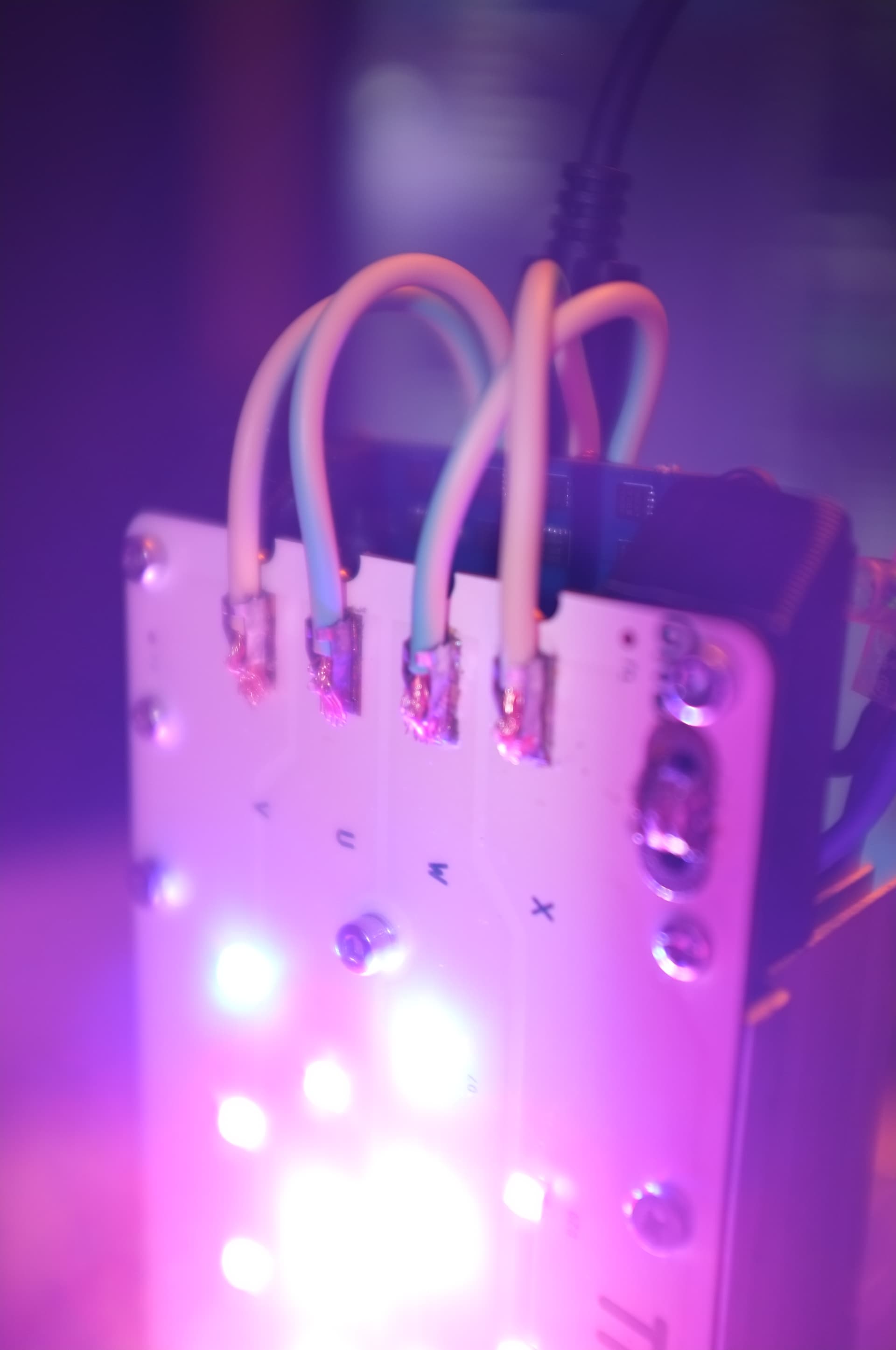
This is a different combination of LEDs. Here two of the strings are only blue and red (3 red / 1 Blue), while the center two strings are red, white, blue. It really is hard to depict just how bright it is. I can only photograph it, if it is dialed way down to driver.setPwm(0.3, 0.3);.
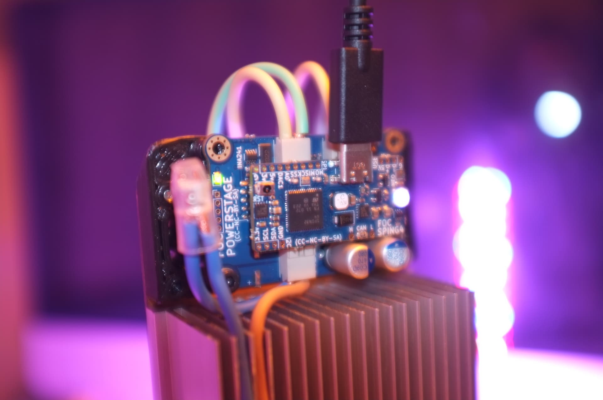
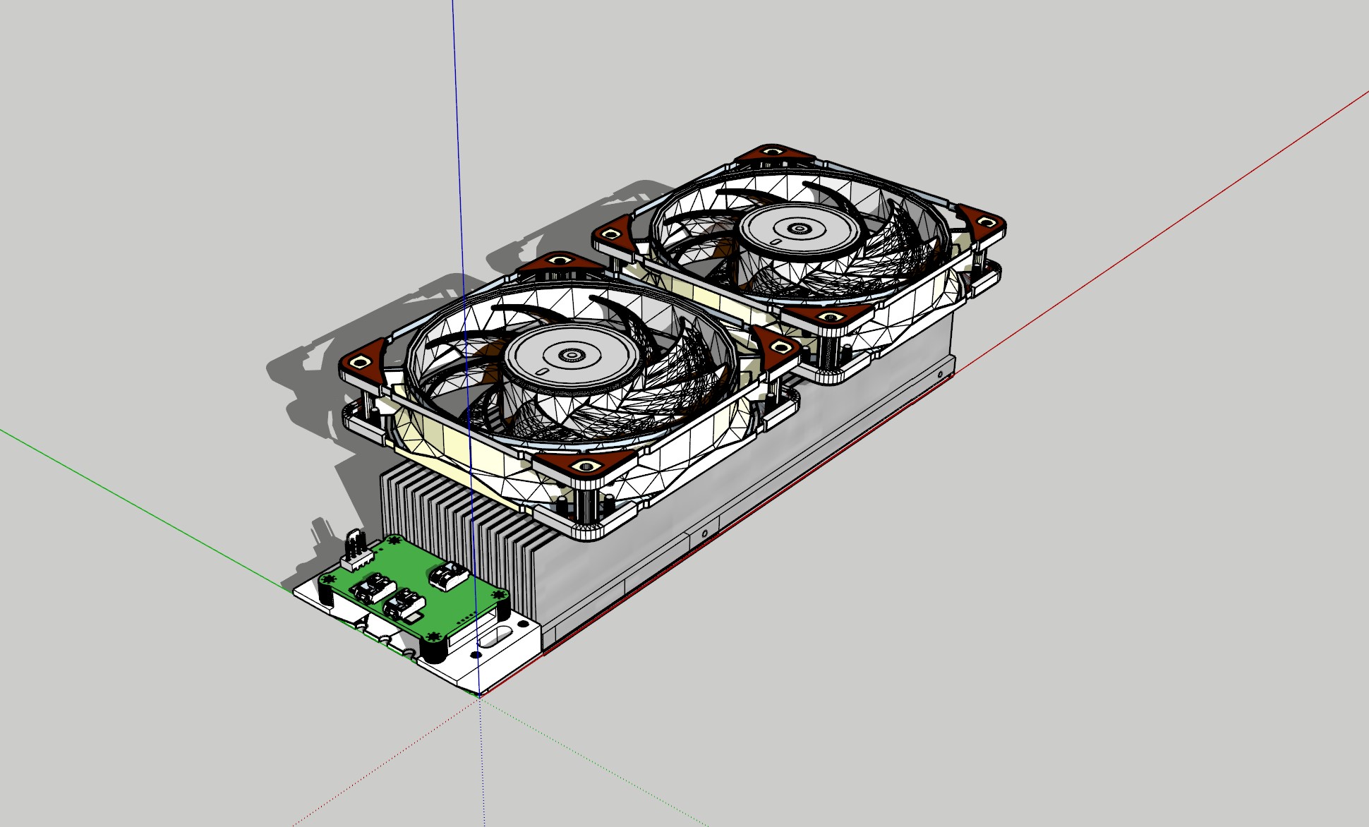
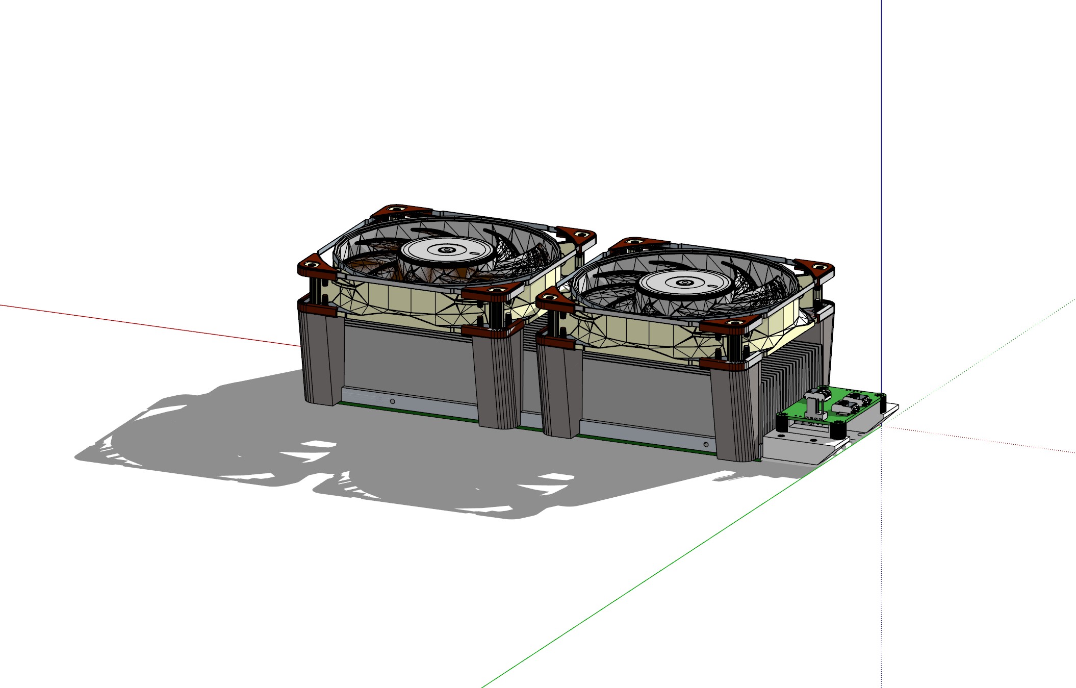
3D printed a small mount for the Field Stack.
There is a significant difference in output achievable with or without active fan cooling. Kinda self-explanatory. Would like to measure the Photon Flux Density, but I don´t have a Quantum sensor. If you have a good Quantum sensor (PAR - Photosynthetic Active Radiation), I would love to borrow it somehow ![]()
Naturally the advantage of using SimpleFOC to drive a string of high-current LEDs with a half-bridge is not dissipating heat/energy trough a limiting resistor. This again effects the output achievable, since heat is the limiting factor.
THE GEM - Smart LED Grow Lamp[Light&heatsource] | Hackaday.io

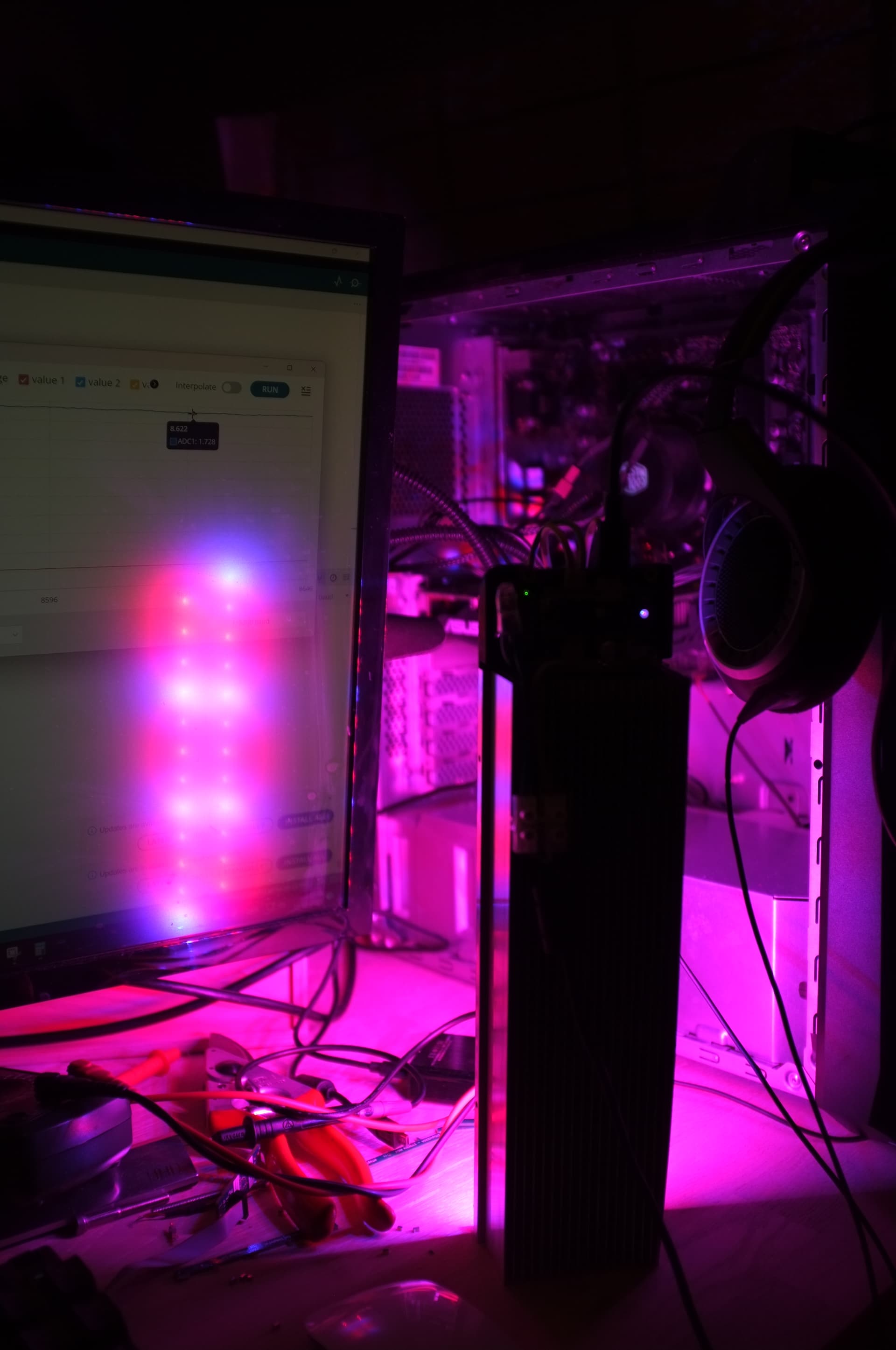
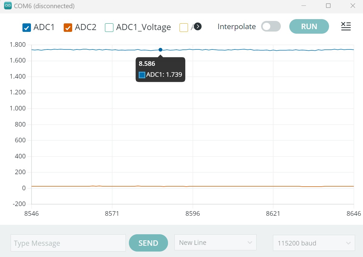
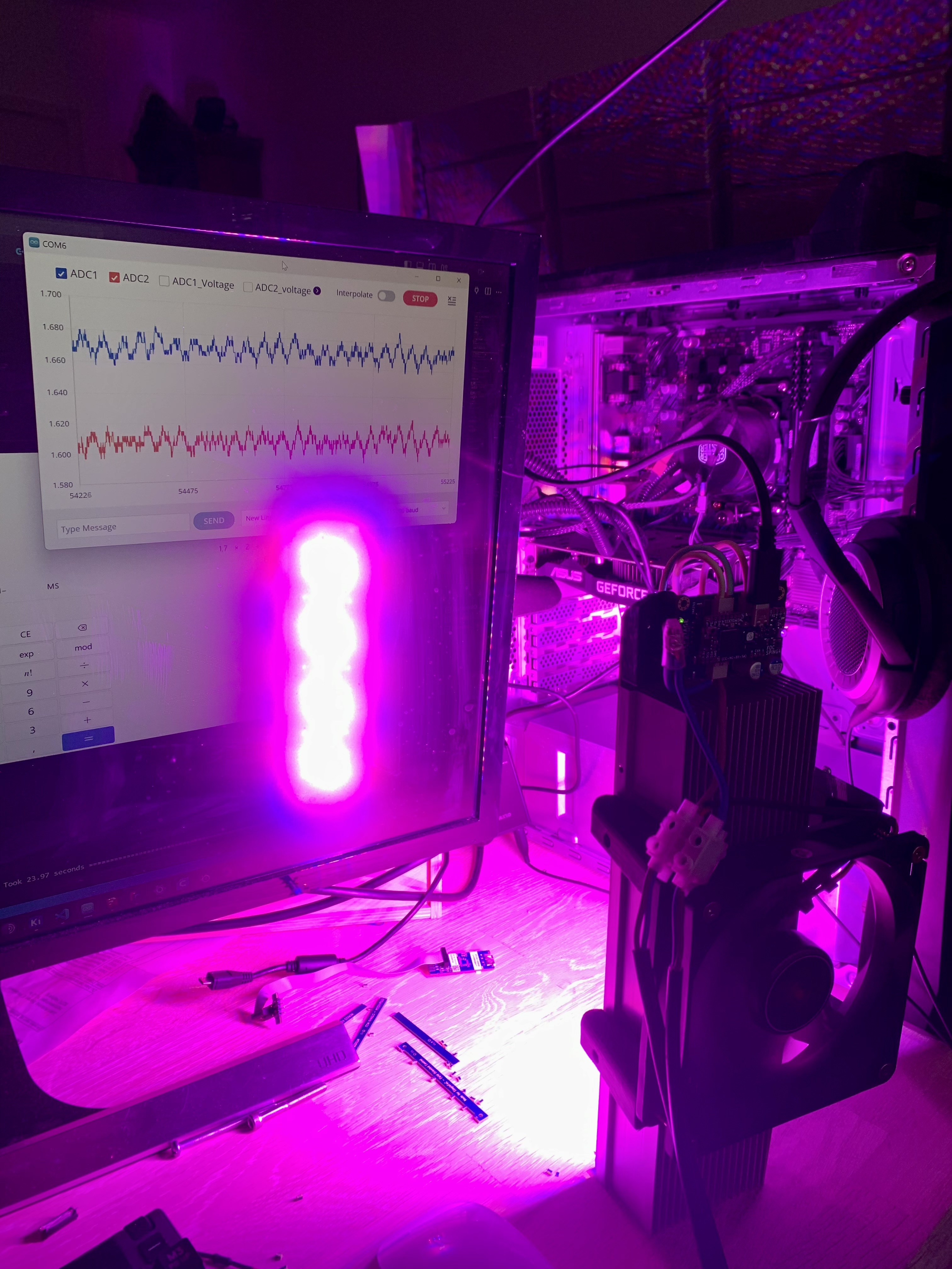
Ok, im starting to get some useful ADC readings. Had to oversample to MAX 256 and use a moving average filter to get stable readings. The readings are consistent with measured voltage on the current-amplifier output.
What strikes me is how low power consumption is compared to actual brightness.
The photos does not do the actual output justice. This is running driver.setPwm(3.4, 0.2);
(PSU is 12.3V. with a 4.16amp rating.)
Values are in milliAmp. Running the Red/blue string at 1.74 Amp, the heatsink is getting luke_warm.
I think it is possible to, maybe, push it to 2.5-3.0amp per string w. cooling. That’s “only” 123-147wattt.
Cant wait to measure the actual Photon Flux output, I think these LEDs are freaking efficient.
I recon two of these can easy cover a decent grow area for eg. 3 German plants ![]()
In theory one could fit two 80x80mm fans on these small ones.
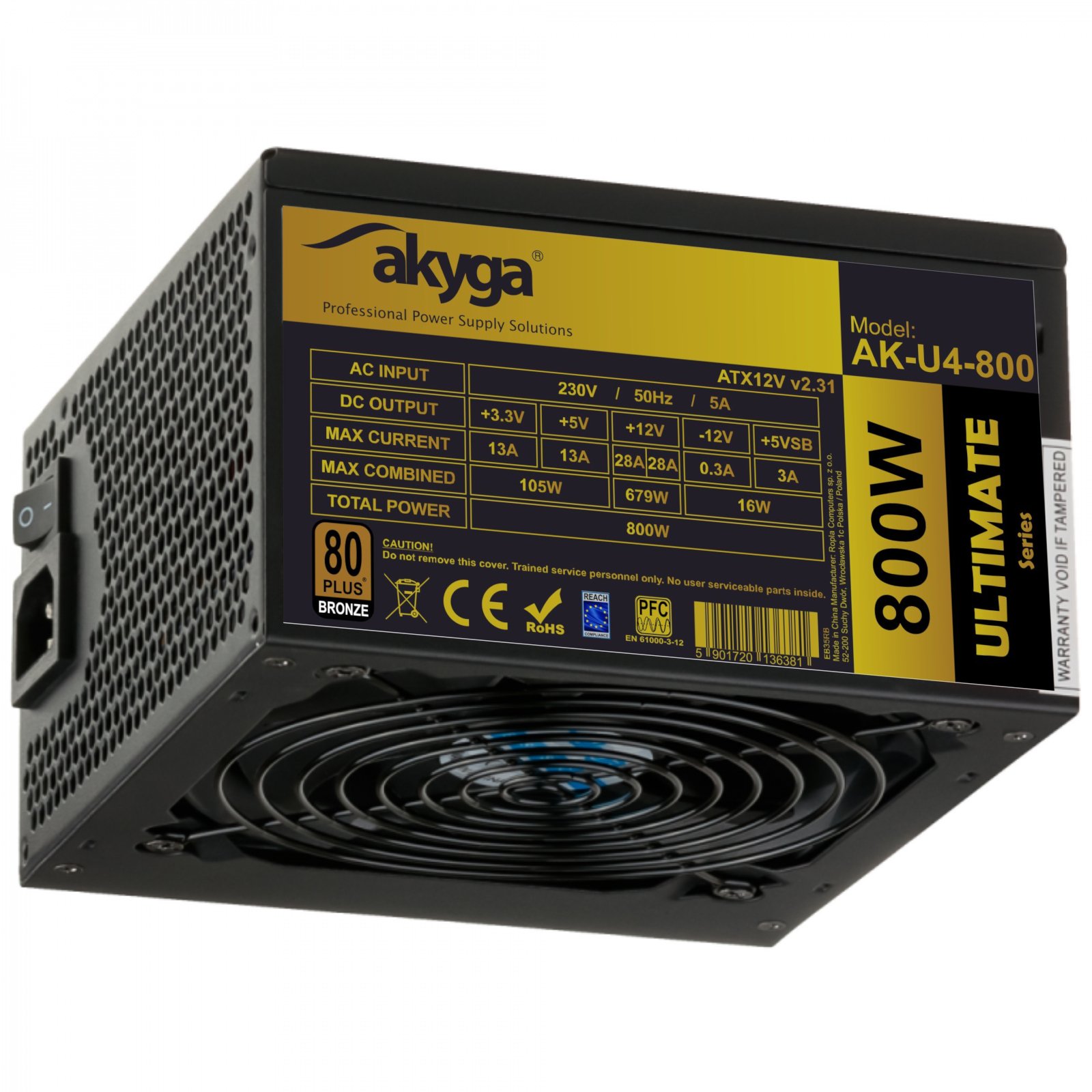
The larger one is twice the size (twice the LEDs). But it will push the field stack power_terminals, so I most likely should make a custom powerstage for the lamp. I probably will. The idea is to run the lamps on a typical PC PSU. All it takes is a resistor to trick it, to turn on. Lots of folks have old functional PSUs, from former PC builds, just waiting.
Those ATX PSU usually have powerful 5V and 3.3V outputs. The 12V output is often limitted to 10-15A.
If you can get them cheap, it’s worth it, but I prefer Meanwell LED PSUs (adjustable Vout)
Do you know, if you can use “any” UV-LEDs for plant-growth?
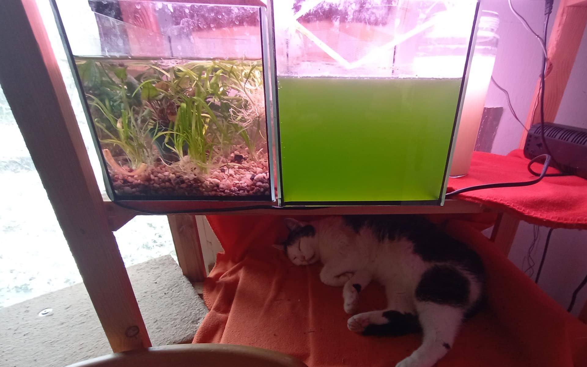
Last winter I have used UV-Ledstrips to grow Chlorella Algae for my fish-pond winter guests. It was quite succesful, but over time, I got more and more blue algae…
UV-light is usually used for killing microbes/bacteria etc. not for photosynthesis. Or curing some epoxy’s.
Oh no, this is a typical PSU. It has 2x 28Amp 12v output. Not that you would normally have that much grow light. The idea is to keep the fan in somewhat low RPM.
The only downside to 12v is the need for thicker cables. Still 10Amp is possible through standard wires. I’m more concerned about the large (double size) lamp. If it pulls 20Amp 250watt it will need beefy cables or two standard wires instead of one thick. Another possible way is to place the same amount of LEDs on the large one, just on a larger area/larger heatsink.
The limiting factor is heat. Not just in the lamp, but around the plants as well, so it’s about finding the right balance.
I know that there are special UV-C lamps for that purpose. The others are either UV-A or UV-B lamps.
But you are trying to mix ‘grow’ light from RGBW LEDs?
These are Cree XP-G3
I’m thinking the custom LED power stage should not have current sense, but instead break out those analog pins for thermistors. Driving the lamp is kinda like heating a 3D print hot-end. Another temp/humidity sensor could be tied to the I2C port.
This power-stage could be used as a build-plate/hot-end Klipper node in a print setup. With the thermistor already in place, they’re 3 analog ports, so one could do a dual nozzle arrangement.
You could easily do 24V
Or make it into front/tale lights ![]()

Ok time to test the ATX PSU.
Im seeing a pretty high voltage drop on the wires. I quess that was to be expected with 12V.
So the input voltage is needed to calculate duty cycle. But if there is no current sensors. Then we need a key to run the LED strings without, using a known current consumption.
From the data, it looks like the PSU is fluctuating a little bit. This is with a 27Khz switching freq.


Pushing all 4 strings with a aproxima total 6.4 amp draw. This is hurt your eyes if you don’t use sunglasses bright.
Waiting for proper Noctua fans in the mail. The one I’m using now, is a two wire, so it’s running loud.
Heatsink is cool. LED plate is luke-warm.
EDIT: The area around the white LEDs are getting warmer then the BLU/RED. In the datasheet it also clearly say that the white´s has higher heat resistance. Its difficult to say how efficient these lamps are, before I measure the Photon Flux Density.
Hmm.. I should probably try to make the bridges fire in sequence. The 8 PWM pins are already complimentary. At least two of the bridges should be asymmetric. I think maybe it’s possible to invert the PWM puls?
That should put less strain on the PSU, making the current draw smoother…
Maybe it will make sense to puls the separate strings independently while at full brightness. Like give each string a +20% wavetop for like 1 or 2 sek.

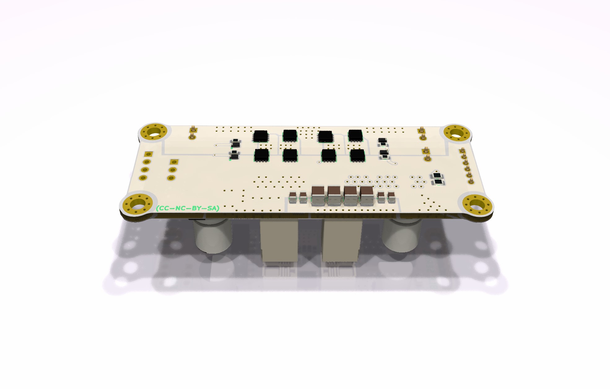
This is with the Infineon dual FETs.
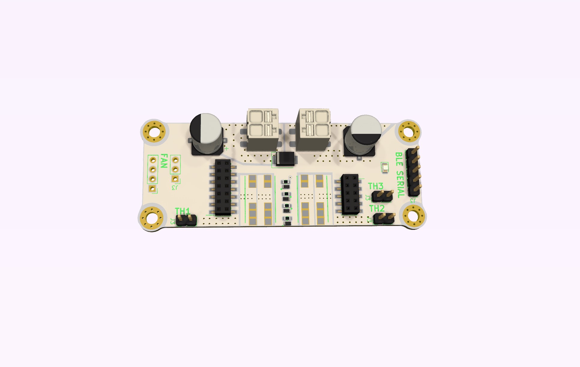
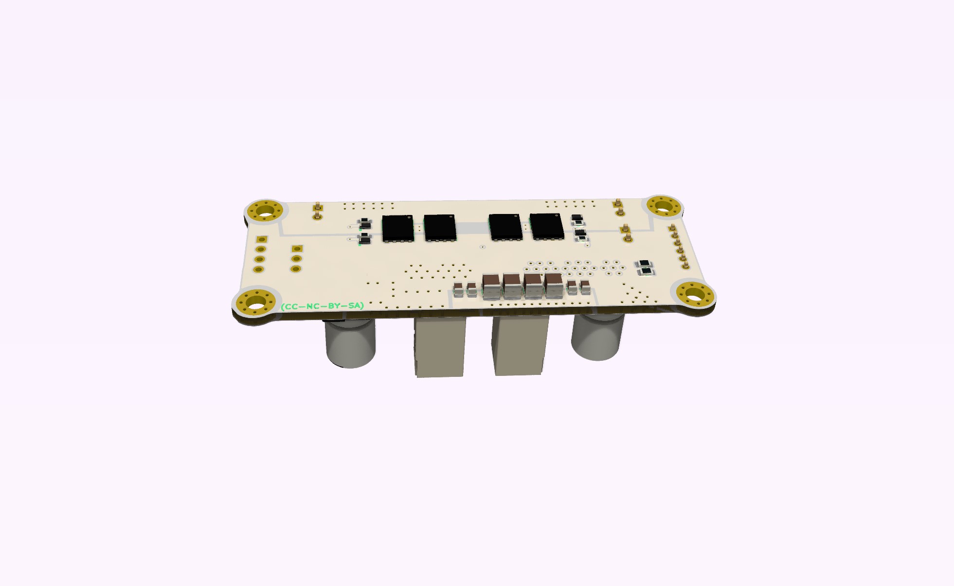
EDIT: It actually makes better sense to use the same Vishay package, just 40V rated.
This means I could make a 24V MAX version of the Field Stack, which will be significantly cheaper, compared to 48V rated components.
Usually hot-end heaters are at the most 24V, so those 40V FETs should cover that scenario. For a typical 3D print stepper setup, 24V is really sufficient.