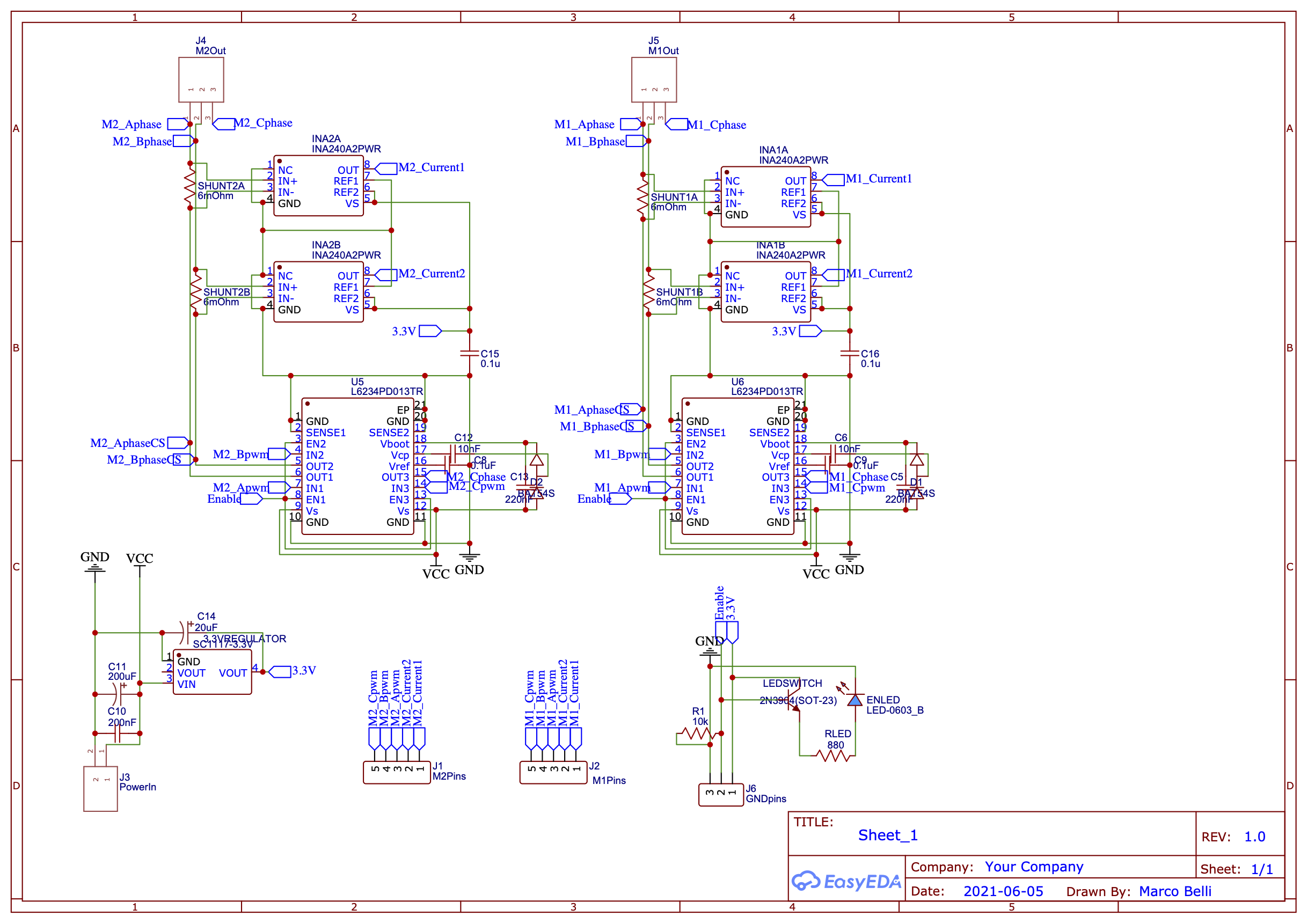
I’m starting a project with teensy 4 and a bunch of BLDC motors, and while I’m at it I am designing a custom clone of the simpleFOCshield v2 that can drive 2 motors and without the features that I’m not gonna use. Since I don’t have much experience in pcb design was hoping to hear your opinions..!
(I know the schematic is a bit of a spaghetti dish, I just threw it together a bit fast to see how it would turn out…)
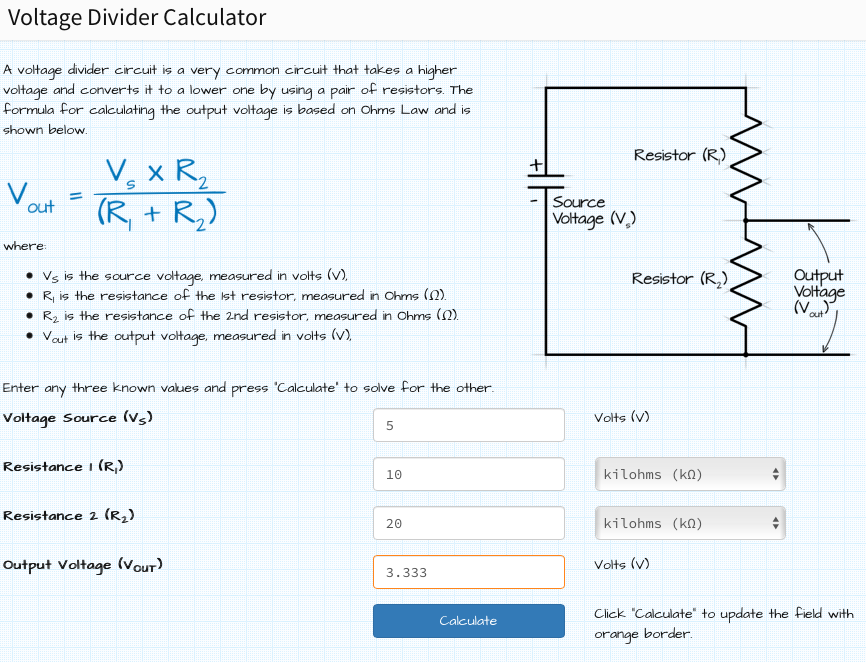
My main concern is about the current sensing, since the teensy analog In pins have a 3.3V range I thought to just scale the output of the INA240 chips from 5 to 3.3V with a voltage divider, Is there a better approach?
it’s not suggestted, but you can still use it. you need to buy high accurate resistors(more than 1%) to keep your results in the right range, and better change to bigger resistors for R1,R2…
Another option that came to my mind was switching the 5V for a 3.3V regulator, so that the voltage reference of the INA240 is 3.3 (and the Output in the 3.3 range right?), or do you think the divider method is better?
Should I account for this change (any of the two methods) in the software somehow? Because I looked through the library code (InlineCurrentSense class) and nowhere does it ask with which voltage reference the current was measured (only the _gain parameter in the constructor function maybe…?).
You can stay at 5v without any problems, you will loose some precision but not too much. The only thing you’ll need to be careful about is the shunt resistor you are using and the the maximum current you wish to measure.
So if you use 5V regulator to power the INA240 you will have 0 current reading at about 2.5V output.
And you will have 3.3-2.5 = 0.8Volt range until you get to the limit of your analog pin.
The best range you can get from a 3.3V pin is ±1.65 which is twice larger. So if you stay on 5V you will lose a bit of precision.
So if you know your max current I_max, the gain of the INA240A2 is 50, you can calculate your shunt resitror to be not higher than:
R_shunt = 0.8 / 50 / I_max
For example, for ±3 amps in both direction you’ll need a shunt of 5mOhms.
Since you’re making your own board, and already plan to use the INA240 amp, why not set everything up properly? It will not add significantly to your cost to do it right.
Here is how I would calculate things, perhaps some others can check that I got this right :
I would try to use near the full scale of both the INA and your MCU. This will improve accuracy and give you the best measurements. You don’t say which MCU you’re using, but it seems you want 3.3V. So assuming you set your VREF (analog voltage reference, almost all MCUs have this) to be equal to VDD, your max output from the INA should be < 3.3V, but close to it.
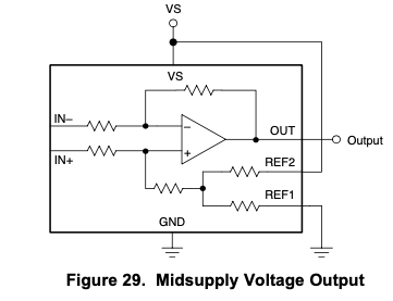
So I would power the INA with 3.3V, and provide the reference as the middle of this:
Now you want to calculate your shunt: What’s the maximum amps you expect to measure? For a L6234 that should not be more than 5A, so lets work with 5A max current. You want to keep the voltages as large as possible, this will be better for accuracy, but the tradeoff is power dissipated in the shunt (as heat), so you have to keep it low enough to prevent overheating. So at 5A, with a shunt of 0.01Ω, you’d get 0.05V voltage drop at 5A. 5A x 0.05V = 0.25W power dissipated. The shunt should of course be rated higher than 0.25W to have some reserves. You will find shunts for 1W in reasonable sizes, so this is ok.
The gain: for a 0.05V full scale output on the shunt, you could use a INA240A1 with a gain of 20 - for +/- 1V on the output side, centred at 3.3V/2 = 0.65 to 2.65V. That’s not really using the full scale though. With an INA240A2 and a gain of 50, you’d be at +/- 2.5V, but that’s too much.
So I would adjust the shunt slightly: how about using a 0.006Ω shunt, for 5A * 0.006 = 0.03V voltage drop, and the INA240A2 with gain 50, for 50 x 0.03V = +/-1.5V amplified output, centred on 1.65V for an output range of 0.15V to 3.15V… I’d be pretty happy with that.
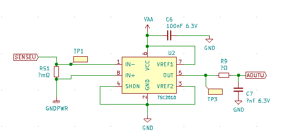
Finally, check your MCU’s analog input guidelines. Usually, you will want to follow the INA240 with a RC filter, as suggested by your MCU’s datasheet. So the final circuit will look a little bit like this:
Thank you, very clear explanation,
I’m using a Teensy 4.1, and the values you derived in point 5 seem perfect.
I never included RC filters for measuring voltages (on the teensy documentation I couldn’t find it), but if you tell me it’s better so then why not (a tip on the R9 and C7 values?).
So in the software I just gotta change the shunt and gain values? (cause the library was based on 5V range input, so shouldn’t some transformation like AnalogIn*=5/3.3 be applied… just a feeling)
Might be best to leave them out if the datasheet does not mention them. I honestly couldn’t recommend values with confidence.
Teensy is a very powerful MCU, you’ll get excellent performance in SimpleFOC from that!
That’s the API at the moment, but the current sensing code is under heavy development, and you can expect some changes and improvements for the next release, I think!
But yes, since the current code finds the middle by itself, shunt resistance and gain are the parameters you have to supply.
I am developing a custom board for a project and I am using a hall-based current sensor instead of shunt+opamp. I am using ACS711. Not sure if I am helping with this information though if you have already set your mind on a shunt / opamp combo. A current sensor provides a lot more flexibility, simplicity and a smaller footprint than the shunt/opamp combo.
Thank you all for your feedback,
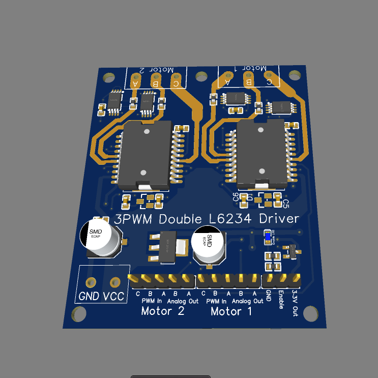
I have finished designing the board so I thought I’d share.
I aimed at a very compact design (52x62 mm) while still trying to optimize thermals, if you have any thoughts, critiques or suggestions I’d like to hear them, since I also have in mind to copy the arduinoFOCpowershield board in the near future.
Just FYI my project involves a robot with 7 motors in the legs (and potentially another 6 motors for the arms) (a combination of low power Tarot4008 motors and some a bit beefier motors), controlled by 2 (or 3) teensy 4.1’s and a ESP32CAM, so wish me luck…
I am not a circuit design expert, just things I notice comparing with other boards I’ve designed. Feel free to ignore them.
As @Franz_Schmidt noted, the power tracks must be either the same length and geometry or wide enough to eliminate resistance imbalance. Even better to create them with vias parallel tracking on another layer, and also use 2oz copper. L6234 chip itself is poorly designed because the power tracks come from both sides mixed with the control pads making it difficult to layout the board.
Inductance chokes (smd ferrite beads) may be useful on the output, I don’t see any voltage spike protection. Your motor may experience sudden breaks in directional change which will shoot emf back into the driver and destroy it.
The varying track width is cause I just thought “power is gonna flow here so if I have space why not give the track more surface area to unload some of that heat off of the small driver pins…”, didn’t think about higher stuff. I’ll take it into consideration.
I thought about voltage protection but in the end decided I didn’t really need for my use, maybe the next in the next high power board.
If you have decided to commit directly into copper bypassing the breadboard stage and no protection perhaps consider breaking out the drivers as separate single surface thin profile mini boards with small pitch headers because if you fry one of them the whole boars with a healthy other driver will be useless as a broken driver may conduct in unexpected ways. This way you can pop in and out the drivers if/when they fail.
In terms of the phase tracks, if you’re actually running 4A, then you’ll want at least 2Oz copper.
I would cover them with solder mask. If you use 2Oz copper you shouldn’t need to add any extra solder to the tracks or anything like that. You can always leave a blank dot to have a test-point if you want, especially on the track between shunt and driver this might be a good idea, then you can measure the shunt voltages with your oscilloscope to check on the INA…
Even better, put some keystone test-points that let you hook your oscilloscope probe nicely. I also like to give my boards a place to clip the oscilloscope ground - I think a nice way can be to make the mounting holes (or one of them) with a pad around it, which is connected to ground. Its a zero-cost feature that will be really helpful when testing.
I can’t see the bottom of the board or underneath the driver ICs, but they have a thermal pad on the bottom, and I would place a large copper pad under this, with a bunch of thermal vials leading to an even larger copper pad on the bottom of the board. This is to help dissipate the heat. I believe the thermal pads should be connected to ground.
I guess if you reversed the sense of the LED (e.g. it indicated the disabled rather than enabled state) you could save the transistor…
I see always 2 of your INA240s are sharing a decoupling capacitor - very economical but given the cost of a capacitor, I would give them one each, and as close as possible to the 3.3V/GND pins as can be achieved. I also think your L6234s will feel very sad without decoupling caps.
Excellent point. If he can put the ground on a separate 2nd layer and punch vias and run the signals on the third layer it will quiet the board quite a lot. Split power and signals and use the fourth layer if really needed buton this board three layers are enough. may be copper pourthe 4th layer for heat dissipation? yes i know, too many cooks, easy to give advice from the bleachers.