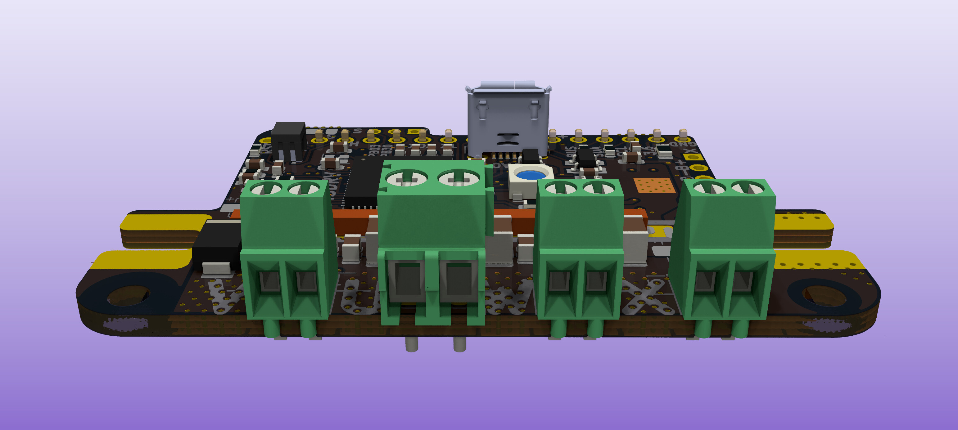
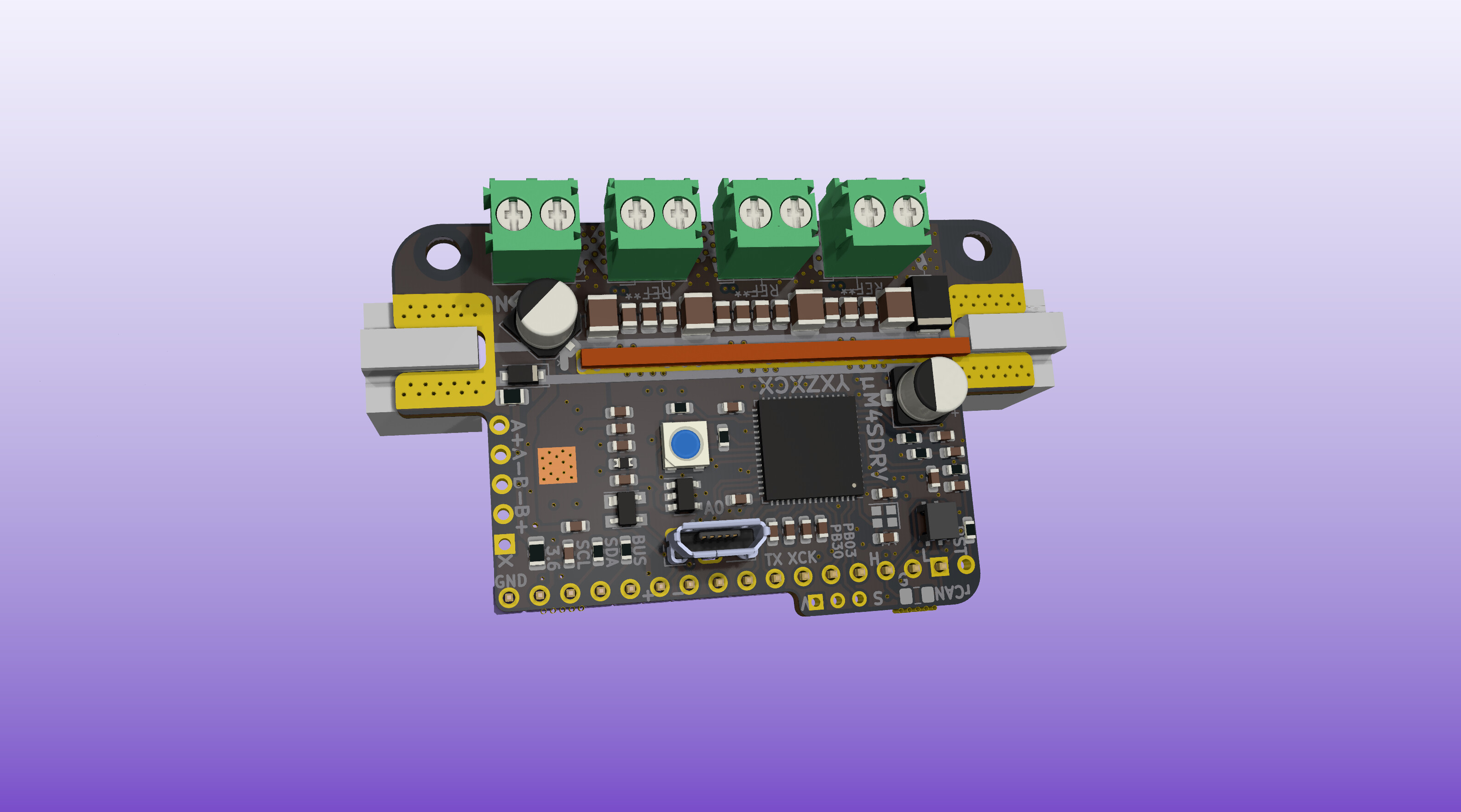
Finally found a format i agree with. These bridges do the trick.
The mounting holes fit on the back plate of a nema 23.
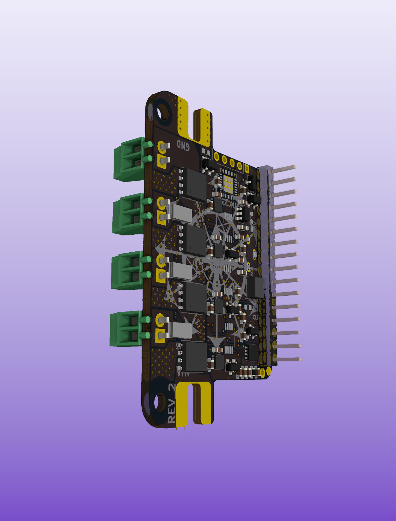
Finally found a format i agree with. These bridges do the trick.
The mounting holes fit on the back plate of a nema 23.
Pitch 2.54 vs. 3.50 Terminals.
17.5amp per termnal, 35amp total per bridge, MAX. That´s pretty decent.
Hey Juan-Antonio!
Very cool design!
Do I understand correctly that you have 3 analog hall sensors, and plan to attach magnets to the outside of the motor? Won’t this be quite imprecise? Is this a common setup? I’m not familiar with this idea.
May I ask why you don’t use a magnetic encoder chip, like the AS5048 or similar? These chips will work with a single, small diametric magnet, and are very fast and precise… You will get 14bits of precision, more than 16000 steps per turn, and the output is absolute.
Hi runger
Yes, that would be possible, to connect a encoder chip. 16000 steps / 40mm = 400 steps per mm.
The reason for the 3 hall sensors on the board, was initially for linear 3 phase commutation.
Now i realized, that the overall dimensions off the board fits on a NEMA23 backplate, and that the sensors can align with the motor shaft center. If it should work, it would need a 3D printed magnet to shaft holder with maybe 12 magnets (depending on constellation).
The project has moved a bit back and forth. See her : THE GEM - Smart LED Grow Lamp[Light&heatsource] | Hackaday.io
With these new switches from Infineon, the current consumption should be covered for some serious LED dimming (Resistor-less). And the 40V rating makes 24v DC motor well within specs. The TVS diode has a 38.5 clamping spec.
The ADC on the SAME51 can make 1000 samples per second. At high rev. that might be a concern.
I thought maybe there is a hardcore DC motor nerd, who can help with the math (coding).
The way i figure. We need to map the analog samples to a fraction of the full turn. 30 degrees (40mm / 12 = 8.33mm * 4000 (12bit) = 33320
For a regular 1.8 degree NEMA23 stepper (200 steps per rev.) Microstepping to 128 gives 25600 steps.
Edid: The wire lugs for the main PSU power lines are 65 amp @75 degree, rated. Next size is 85 amp rated. 65 amp @12V is 780 watt ( Watts/Volts/Amps/Ohms Calculator). My main priority is the agricultural lamp specs. In that regard 780 watt is way above, what is mandatory. Not to say that a above spec. buffer is not in place. It is. We do not want excessive heat.
Edit 2: Ok i like the sound of 85 amp. Bzzzzzz !
Edit 3: The focus of this application is around 1000mm sek. actual movement MAX. So 4 samples per 30 degrees. 700mm sek is also within target.
Edit 4. 1000mm sek will then be 25 rev. sek.
Edit 5: Maybe its simply not fast enough. How fast is your encoder 14 bit ?‘’
Edit 6: Ok i see the AS5048 has a 11.25mhz sampling rate. That´s 11250 cycles per secund.
Edid 6: So what is the function of the RAM. (RAM - Wikipedia, den frie encyklopædi), Time is random. Just saying.
Time is volatile: Since gravity prevails.
It kind of feels like your 3 hall sensors are in place of normal hall sensors. These sensors are typically placed on stator to measure magnet pole pairs on rotor. I.e you are discovering position of stator coil w.r.t to rotor magnets. This is what you need for sensor alignment. Putting magnets on board probably won’t help with getting that alignment.
Hi Owen
Yes i agree, in a 3 phase commutation configuration. What I wish to achieve using analog hall sensors, is to give a stepper motor a precise angle reference. For a stepper, we do not need commutation. The sensors will be placed apart to cover 30 degrees. I must admit, i do not know how the sensors will behave. There are different variations with regards to sensitivity. I think the magnetic fields will arc, and thereby create a usable output.
Edit: Regarding speed. Since the steppers do not need the hall sensors to move, it is basically just for controlling if any steps was skipped. So the measurements will be needed at the end of a move. Eg. before placing a part on a pnp machine.
I’d say so, but I’d also say the 17.5A capacity of the terminals is low compared to the 100A capacity you plan for the busbar… doubling up terminal leads doesn’t directly double their thermal capacity either…
Perhaps specific high-current connectors, something like AMASS XT90 type plugs, or just really big solder pads to directly connect thick copper wires would be safer choices?
35 amp continuous is still maybe 50 amp peak (10 sek punish)
50 am peak (10 sek) is 1200 watt (24 volt).
Depending on rotor windings turns and gauge ill argue it will deliver quite the punch. But it all depends. Can you sync. 4 motors, 4 controllers on the CAN FD bus?
Edid: Ideally the vehicle (Mooncart a.k.a. The Bullit) should have one gearing on the rear and another in front. This does introduce a layer of complexity. The controller is 120mhz. Do you think it will cope. Is a 12mhz crystal mandatory? There is already a typical 32,768khz in place?
2nd Edith: The TMC2209´s could potentially be used for headlights and or spoiler (Rear Airo Fin = RAF)
That should work, CAN is up to 1MHz.
Yes, a SAME should be able coordinate 4 motors via CAN, if I understand your question correctly? At least for a wheeled platform this should be no problem.
Ideally, you want at least the 32kHz external oscillator. The SAME can generate other frequencies it needs from this. Which SAME are you using?
That sounds amazing and so very time consuming.
If this, at this point theoretically, one person + luggage carrier, had the controllers inside the hub wheels, mounted on the stator, the wire going to power the hub could be something like AWG 6 or 4. The coils could then be soldered directly to the controller and get very close to the switches. The closer the less resistance.
Which gauge copper wire would you choose for a 24V 45 ampish motor?
Here I have made a simple calculation using 2.59 mm diameter copper. This seems like a lot of torque per coil? How much heat can a coil realistically dissipate ?
Ding ding ding ![]() (The sound of coils firing).
(The sound of coils firing).
If designed into the stator, IMO a 100 amp fuse per phase would be logical and would create a point to attach the 2 x AWG 16 (1.29mm). It would need a 3-5W sense resistor for sure.
https://www.mouser.dk/datasheet/2/348/psr-e-1139146.pdf
Maybe 0.3 mohm 3W
Thinking about all this; It should just be one axis (front or rear) driven by hub motors. The other axis should be attached to the chassis and some sort of gearing.
BOOOST!
Edith: The real question is; how many and large cap´s are needed?
In a 1412 setup; how much torque do my friends dog need for forward movement carrying a large battery pack ? Uphill?