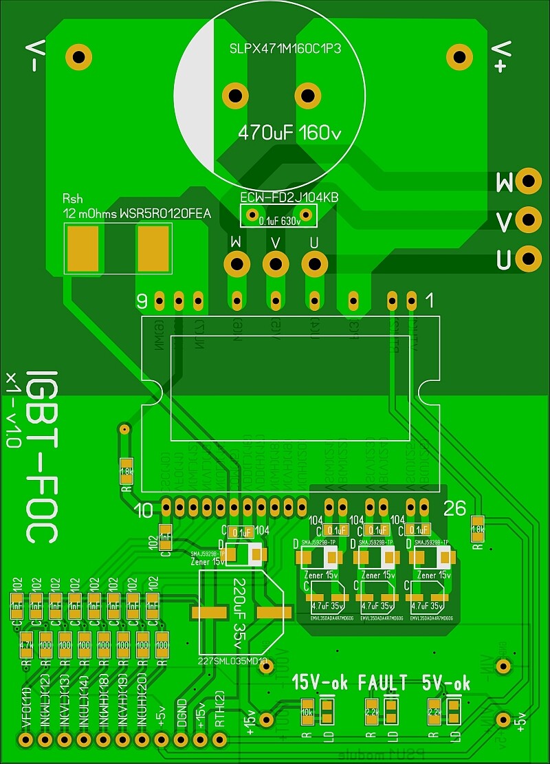
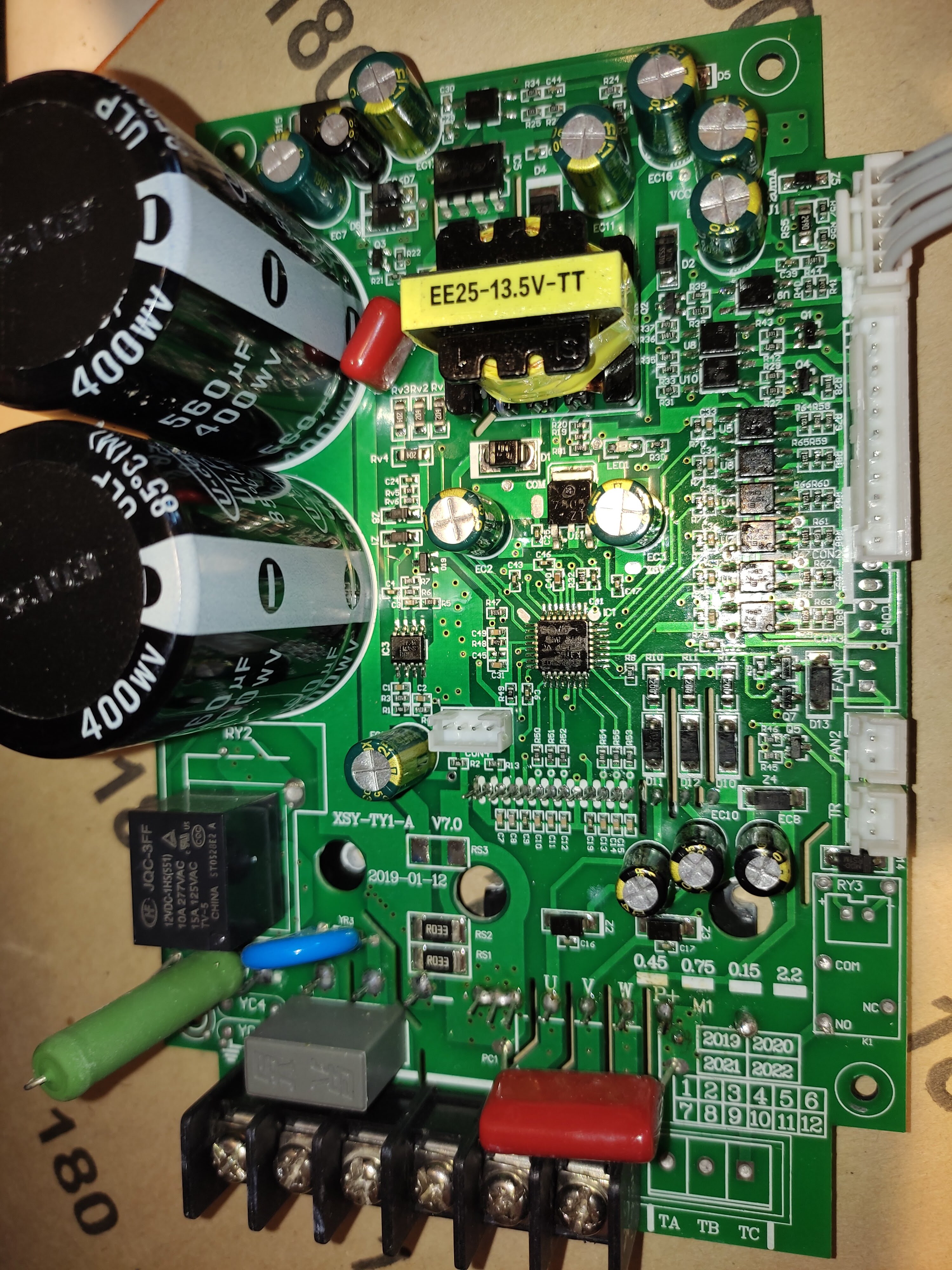
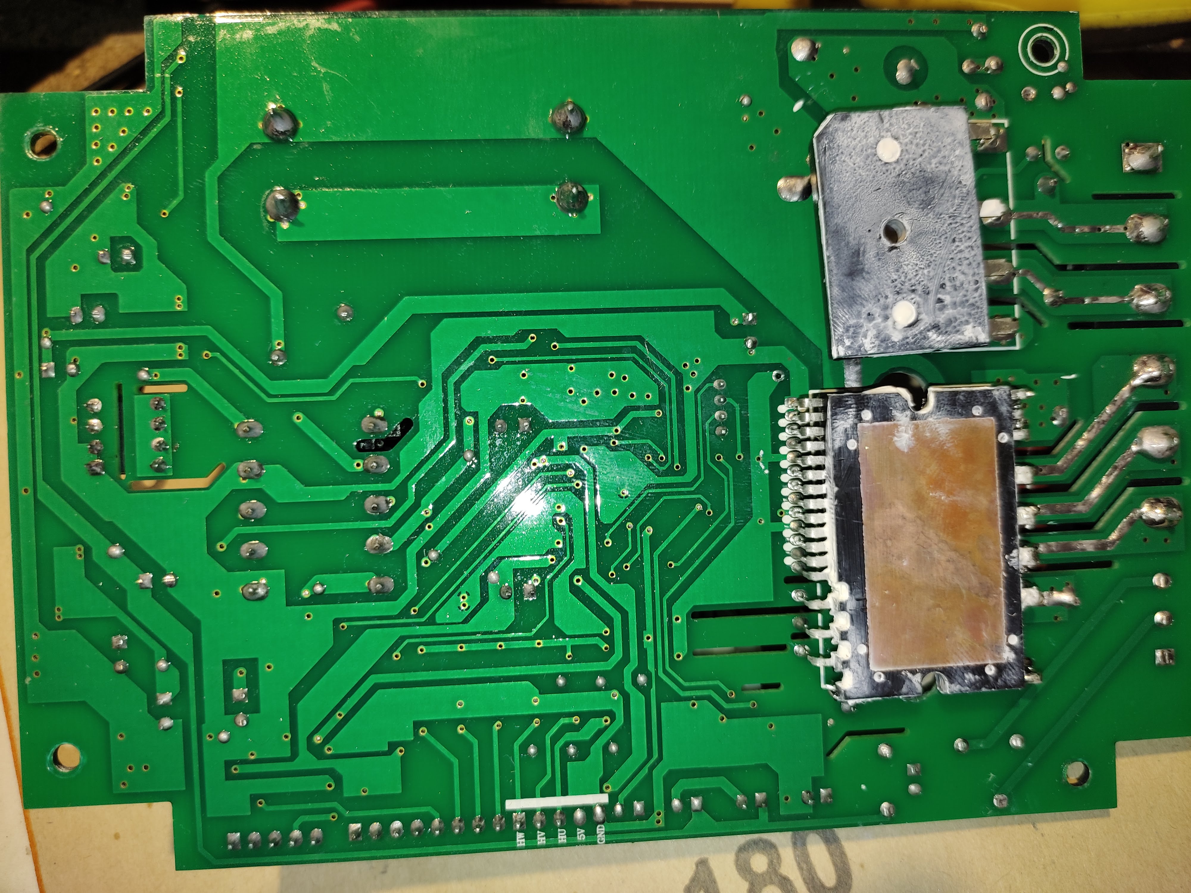
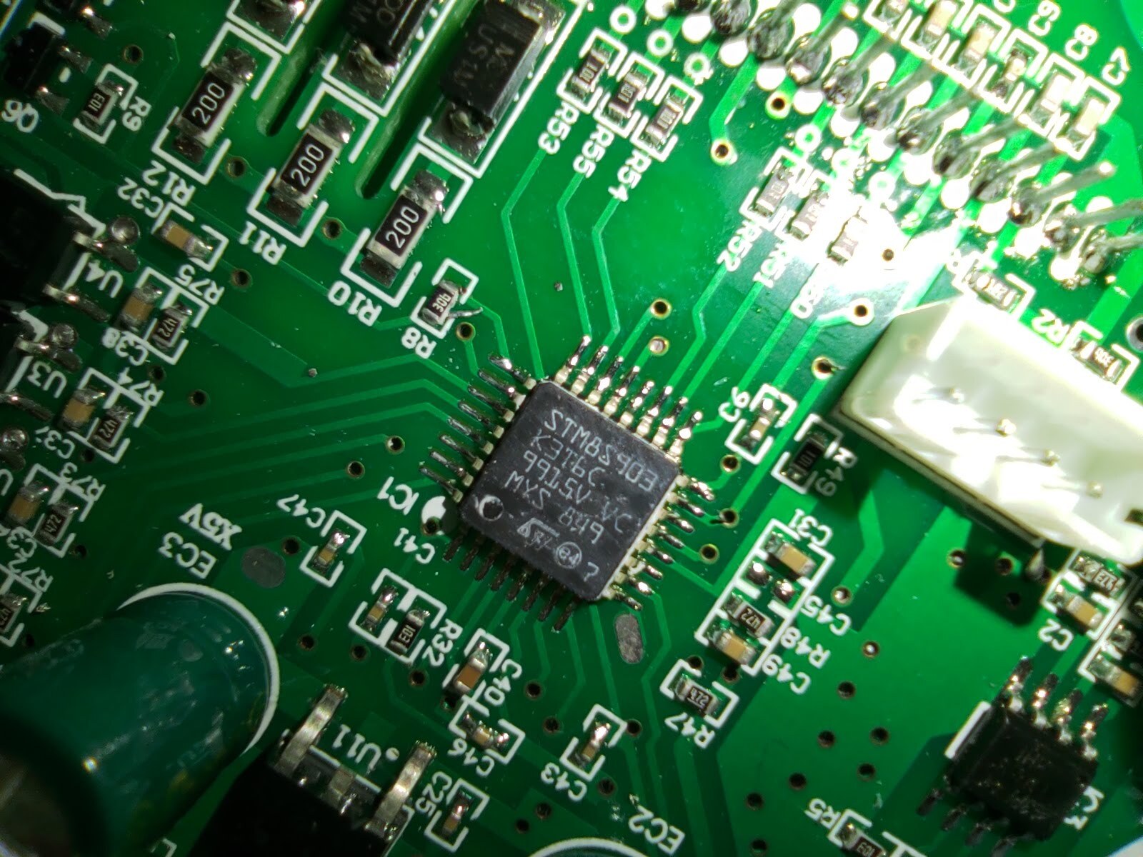
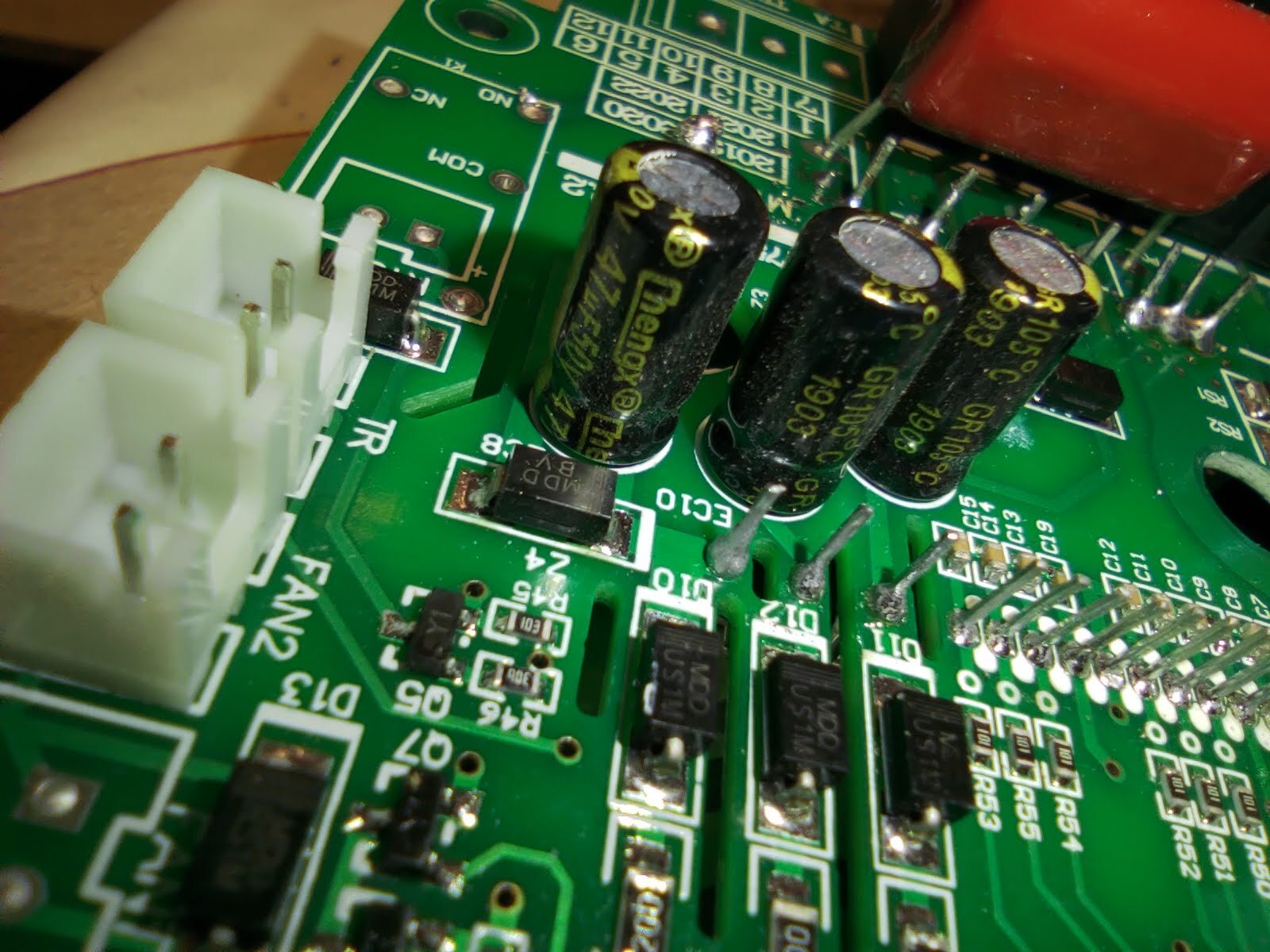
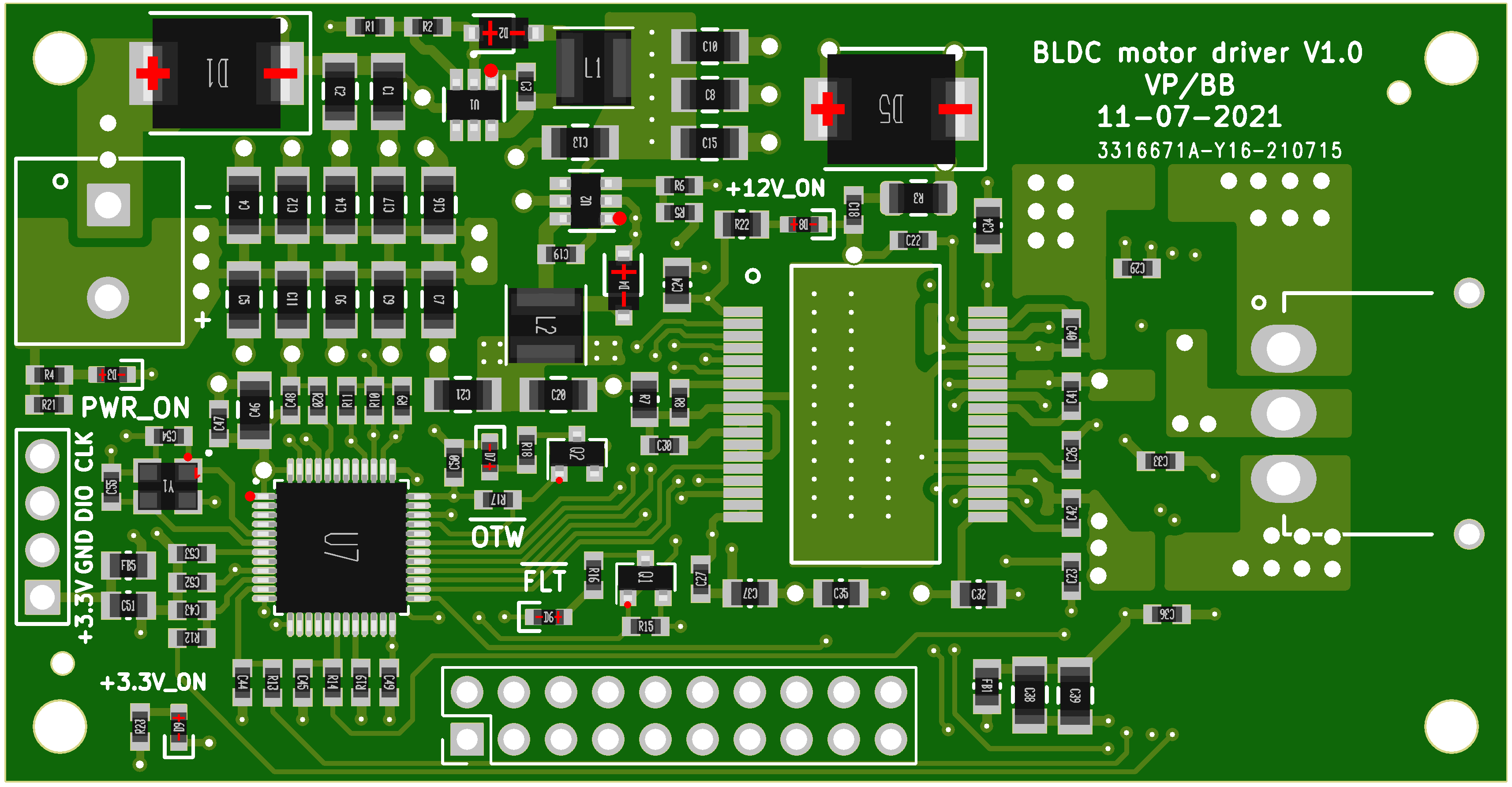
I use sprint layout 6.0 for the design… don’t even have schematic lol
All parts are manually created from measurements of the real parts in my bin.
I use sprint layout 6.0 for the design… don’t even have schematic lol
All parts are manually created from measurements of the real parts in my bin.
The manual routing one, right? That’s hardcore. I’ve always been amazed at the ability of some people to perform high-level design in their heads and commit directly to product, and then it works when you plug it in. That’s quite rare.
Do you reflow everything yourself or order a bare PCB with some of them added by the manufacturer and then add the extra parts?
All my boards are designed by hand, and thankfully the sprint layout 6.0 has electrical testing of traces to make sure they are not touching to each other or that the grounds are not floating etc… I like manual routing, there are electrical considerations that the auto routing can not predict…
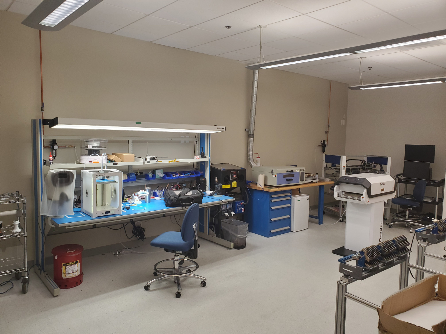
I stencil, populate and reflow my boards on my own… in my lab:
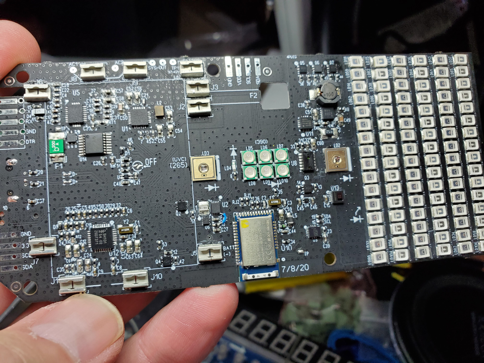
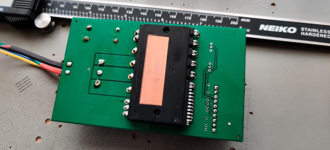
The most complex board I designed is this one with qfn and all 0402…
(Yes there is a tiny blue bus wire that I used to bypass a chip on there  )
)
I am envious. My board design process is calling an engineer and explaining what I want, unless it’s something really small i can do under one hour myself and order to smt.
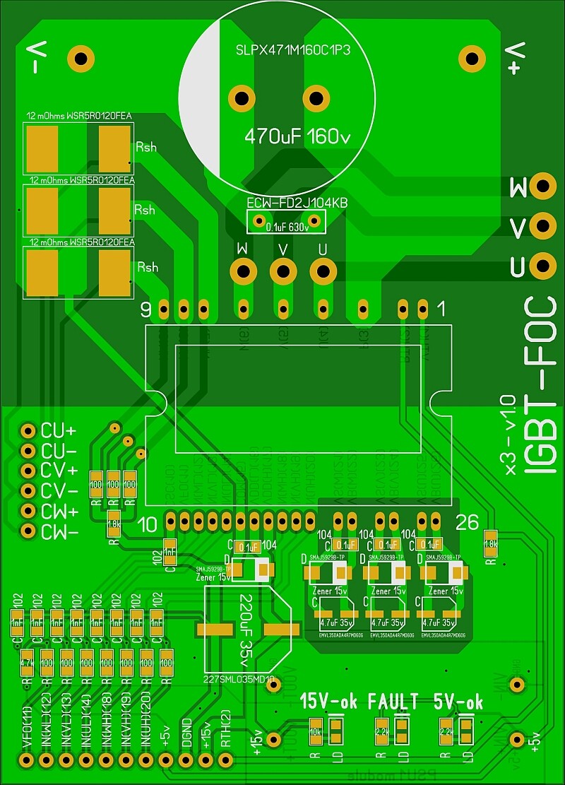
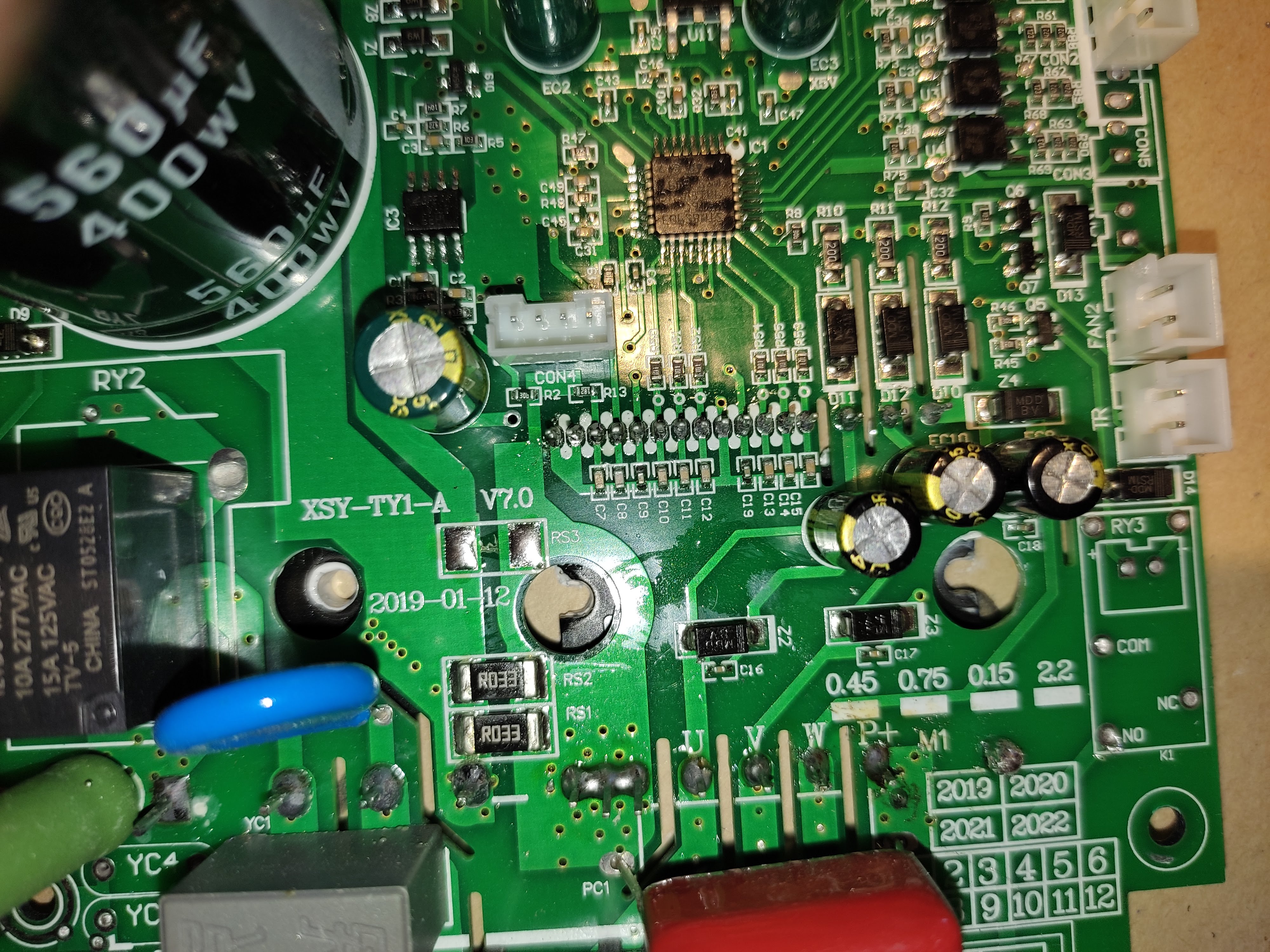
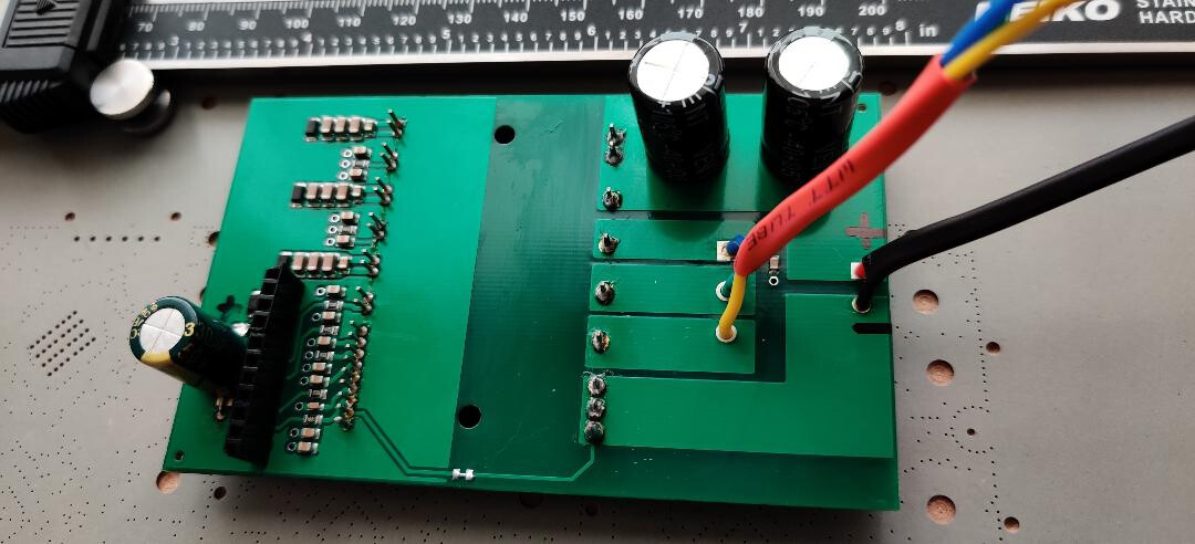
Remember, the current sense resistors layout must be symmetrical and the copper between the resistor and leads has to be the exact same length else you will get a bias. This is not a production board so it will work fine. Another option is to keep the copper bare and pour solder, that’s dirty but works, or increase the thickness of the copper to 4 oz, or increase the layers and dedicate two thick layers with vias. Or keep the single resistor and put the three phase resistors inline with the output. This way you have the total current and individual phases separately.
Don’t listen to my advice, I am just observing, these are not suggestions. The board looks great.
Yeah, I know about symmetry, but for a prototype to test, its fine. Will discard this board after a few tests anyway 
The traces are calculated for 7.8A on the critical points. I’m hoping to operate this on 75v so currents will be less.
Just need to figure out the current sensing stuff…
I never understood why don’t the manufacturers just make thick legs and put some space between and instead make those tiny leads that make me uncomfortable looking at them. It will be so much easier to solder.
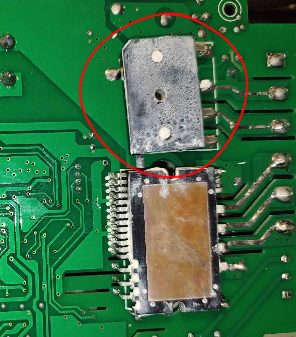
If you want the part number i have to look again, because I thought it’s just a rectifier probably 10 or 16 amps rated
Yeah, I wonder what they use…
Here is a part that could be used for this and is within specs for 220v single phase
https://www.digikey.com/en/products/detail/diodes-incorporated/GBJ1504-F/815140
@Valentine got any timeline when you get your igbt Module prototype up and running?
I will receive my development prototypes by end of this week, and work over the coming weekend. Got delayed, the HW engineer went on vacation. Should have something to show you by next week, I hope, if the board is correct. He discovered an issue in the last moment before taking off to Mediterranean, and that delayed my order, then the manufacturer messed up the board, a comedy of errors. It’s one thing drawing on paper, another to actually produce a finished product, hahaha.
My current roadmap is to use st32f103 and if it works I will ask him to create a more comprehensive solution with an integrated MCU and IGBT power stage, may be some extra protection, and a thick copper layer.
My backup plans are to go back to a mosfet solution, I have two integrated power stages I will use
FTCO3V455A1 – 150A continuous drain
MTI85W100GC – 120A continuous drain
combined with a driver, probably one of the TI drivers, and a fast hall-sensor current sensing. At least one of these should produce a good end solution that will be productized.
Don’t discount the mosfet solutions, because 150A continuous drain @ 40V is something pretty serious. The IGBT is a lot lower than that.
Cheers,
Valentine
Looks good, if it works reasonably well for you then I’m ordering my parts.
Looks good, yeah. Are you planning to add heatsink? It has to be mounted before you solder it on the board…
I was doing some calculations for AC supply, here is what I came with:
Simulation AC 220v 750w PSU
*Updated the simulation file with more stabilized output…
I am still testing, will let you know, I will need some time.
Looks good, how is the igbt driver working?