Yes, aren’t you driving the IGBT with 6x PWM mode signals? It needs that mode of driving. You can’t just strap the low side to ground and only pulse the high side. It makes sense to use the low side enable to charge the bootstrap capacitors to use that in the next cycle…
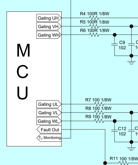
@Thanos I’m using 6x pwm that’s not the problem, what I’m concerned with is some extreme edge case where the high side is on for a really long time and the Bootstrap circuit is discharged and it essentially stops outputting on the high side and it goes into fault because of low voltage on the Bootstrap circuit.
I’m sorry, I can’t imagine how this can happen… I mean you supply Pulses, even if the motor is still and holding angle, you are pulsing say with 15Khz alternatively the high-low side and this charges the capacitors always. If you stop the PWM and supply continuous DC signal, its another story, you are not doing FOC then.
For fucks sake I’m dumb  sorry at @Thanos @Valentine. Now i got it. In the first diagram it’s easy to see (https://www.digikey.de/de/articles/why-and-how-to-sinusoidally-control-three-phase-brushless-dc-motors)
So my extreme edge case doesn’t happen ever basically 
Hahaha, yeah, those Hall-sensor activation diagrams can fool you easily… lol
@Thanos sorry another one i don’t quite get, when I have the motor in position mode holding it’s position i have no sine wave on the 3 motor wires instead i have constant voltages, is that correct?
nope… still 3 PWM signals are holding the motor in place… 
The motor coils integrate those pulses to voltage because … coils!!!
But also the current varies to accommodate for the load.
In a “holding” mode, or close to 0 angular speed the field to the coils is “frozen” in time but you are still pulsing high/low at whatever PWM you specified because different coils still need different open/close to hold the flux at that partial level.
I think you are confusing the resulting sine with the underlying PWM timing to construct it. In the simplest 3-coil case, holding one coil at max means the other two are partially “energized” and you need constant hi/lo PWM for that to happen, your PWM never stops firing.
@Thanos @Valentine i did some MS paint action. do i understand this right now?
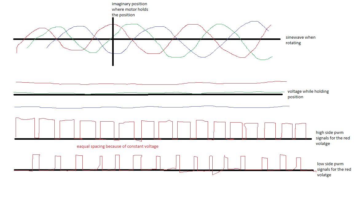
And for the green line the high and low side would be on the same amount of time. One off the other on and so on and so forth.
And the blue line the majority of the time the low side would be on.
Seems correct, yes. If I get time I am actually in the middle of testing my drv8332 board and can post a video of a motor holding pattern on the oscilloscope for one channel.
I think your intuition is correct. This type of controller is not designed for motors that are not permanently turning. Position mode with holding positions is more the domain of gimbal motors and their controllers, and I have never seen such a thing with IGBTs.
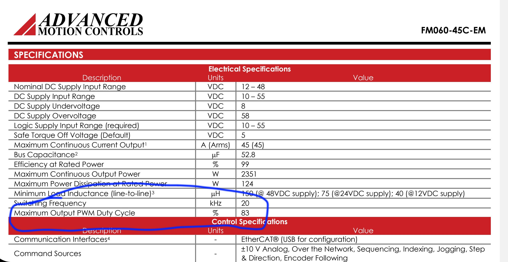
That said, the PWM is of course still active, so the condition you are worried about is relatively rare - holding a position in which one of the phases is at max, and also the current/voltage/torque control outputting a 100% duty cycle. If you set your driver.voltage_limit below your power supply voltage, the PWM will never be 100%, for example.
But in principle it could occur, and you can prevent it in software.
@runger  yes that’s the next thing I wanted to ask when I have supply voltage of 50v and maybe the red one (in regards to my painting) Outputs at 50v then the low side would be of.
An easy solution would be to limit the motor voltage to, say 40v so that the low side is always on some amount of time.
@Valentine @Thanos i have another question, for in line current sensing with 2 sensors at 350v-400v what are my options? i found this (https://www.mouser.de/ProductDetail/ACEINNA/MCA1101-50-3?qs=sGAEpiMZZMsPDRSCoHb1X%2FgeUz%252B5VUvm8sQE3w%2Fv4%2FybHBotsw1cdA%3D%3D)
but its a bit expensive. another option i saw was to create a floating supply to the INA current sense amps. any other methods that keep parts count/cost down?
I am using Allegro however they are not stocked by Mouser, you need to order from Digikey or another distributor that stocks Allegro. In your case ACS725LLCTR-50AB-T may be what you want, its $1.90 and in stock.
Edit: The reason Aceinna is five times more expensive than the Allegro is the bandwidth. Aceinna is 1.5MHz, and Allegro is 120KHz. It is possible to max out the Allegro, I am not sure, at high PWM. I am in the process of testing and I am also curious. However, for IGBT since you realistically cannot exceed 10kHz I believe the Allegro will give you what you need at a lot lower price point, because this is 100us pulse to pulse duration and the allegro response time is 4us and Aceinna is only 300ns, that’s ten times better. I am very curious too because I don’t know how simplefoc synchronizes the inline current reads w.r.t. PWM high/low. Perhaps this is a question for someone who is a lot more knowledgeable of the inline current sensing code internals.
Edit2: I should post this as a separate question as part selection is always very difficult and requires a pretty comprehensive consideration.
That part seams to be only 5v, i found another part from melexis MLX91221KDC-ABR-050-RE, this should work, this part also has half the response time at 2us.
You all got me so curious that I just put together a board and ordered it, hopefully next week I’ll get it and let you know. I am using Fairchild’s FNB33060T. That chip is one huge piece of hardware.