Wow. Incredible. That really opens the door for working with all fully integrated IGBT driver/power modules out there, which were originally designed to work with high voltage motors.
Another external component is needed lol. the zener diodes for over voltage protection, (killed 2 igbts in my testing, but whatever) my next step is a custom PCB with the circuit layout from the typical application circuit from the manual.
Edit, i had the thing working at 7v so low voltage doesn’t seam like a problem.
That’s really fascinating, I had a discussion with the hardware engineer I work with on another project and he expressed his reservation that the 300v IGBT module could effectively work in a low voltage mode. His concern was the efficiency in low voltage mode, that is, how much heat is generated at higher current. Have you had a change to check if they get hot?
Edit: What frequency did you use, the IGBTs efficiency is very sensitive if you run them at higher frequency. That’s why usually people prefer working with MOSFETs.
I ran about 3 amps trough and 2 of these little stick on heatsinks that are included with the odrive where enough for that. I mean as I see it 3 amps are 3 amps and with lower voltage the losses should be smaller. When I have a proper PCB and don’t kill IGBT for stupid reasons I’m going to look into testing the efficiency properly.
I ran it at 15khz seamed fine to me, datasheet says max of 20khz. From my knowledge with working with Siemens vfd’s (Wich I’m 99% Shure use similar igbts) it’s usually fine to 12khz or so and the it’s derated to 70% at 20khz
Wow. 20kHz is actually not bad. The one I am working with (NFAM5065L4BT-D) also lists 20kHz as upper value, which for most practical purposes at low RPM is fully sufficient, e.g. gumball mode. That’s very encouraging.
@Valentine hey, i still have some problems understanding how the gate drive voltage for the high side IGBTs works, i supply 15v to VDD and then this goes to VB (i assume voltage bias) but the rest in don’t really understand why do I need the capacitors and diodes between 21-22 23-24 and 25-26.
I think you understand this better could you please try to explain this to me again.
Thanks for the help
Edit: as far as I can tell from some documents that i found from Texas instruments I need to supply 3 separate isolated floating voltages to the 21-26 pins 15v as far as I can tell, I think the easiest Solution would be to use a isolated DC/DC converter (3 pieces one for each gate)(part number pdme1-s15-s15-s should work I think) and generate the voltages from the 15v supply.
Hmm, I don’t think its necessary in the manual it says its internally isolated…
Internal Circuit Diagram
Three bootstrap circuits generate the voltage needed for
driving the high−side IGBTs. The boost diodes are internal
to the part and sourced from VDD (15 V). There is an
internal level shift circuit for the high−side drive signals
allowing all control signals to be driven directly from GND
levels common with the control circuit such as the
microcontroller without requiring external isolation with
opto−couplers
This is an interesting question. Also during my explanation I will be lying to you a little because I am not sure of your level of background physics. Others on the board may take an issue with this, so we need to be patient.
Remember the mosfet is voltage controlled while the igbt is current controlled.
The diodes (think valves) are to prevent any current flowing backwards so the capacitors can get charged but also not overcharge. May be it will work without diodes, not quite sure, without implementing the circuit and checking with an oscilloscope, because there are diodes inside already which are not specified what are exactly as you could see but the external are zener diodes, not the “normal” diodes. Zeners will allow current to flow “backwards” when an exact certain set reverse voltage is reached, due to quantum tunneling, known as the Zener voltage. I am assuming the reverse voltage is 24V based on the 1N4749 specification. The diode is there to protect the capacitors from overcharging, like a safety valve. Also, if you look carefully the capacitors are 35v max, so the lower zener threshold voltage will let current flow backwards to keep them safe.
The really interesting part is the capacitors, they serve as energy storage to open the gates. At the right time when the PWM is high, each of the capacitors will get suddenly discharged for the duration of the PWM high side pulse and let the electrons stored inside rush into the corresponding IGBT and open the gates. This opening timing logic is controlled by the driver MCU inside the IGBT chip and is very complex and hidden from you. You only supply the high PWM. The power (motor) side current will flow from positive P to the corresponding U, V or W for that time period. If you imagine the IGBT module as a two row (3 high, 3 low) six cylinder, two-stroke internal combustion engine, the capacitors are the ignition coils firing the spark plugs (igbt gates) in sequence, triggered by the distributor (the PWM control signals and driver MCU), igniting the combustion mix (power side electrons) and pushing on the main shaft in sequence controlled by the PWM. The high capacity is to store the trigger energy and the low capacity is a snubber I guess to reduce the parasitic inductance of the electric wiring and prevent accidental discharge. That’s why the diodes and capacitors have to be as close to the module as possible and have some isolation distance to prevent inductance and capacitance cross-talk else you may end up triggering the neighbor IGBT which will lower the efficiency.
That’s why you need a large capacitor for IGBT because you drain it for current, not like mosfet where you use it for the voltage charge and very little current flows.
You need a single voltage source for all three.


@Thanos yes I know that, but in this (https://www.onsemi.com/pub/collateral/an-9084.pdf) user guide under 5.6 in the second paragraph it says: “there are a number of ways to generate the floating supply voltage”
And if I understand it correctly the high side bootstrap circuit is charged when the low side IGBTs are on. Wich means if for whatever reason I want to switch on the high side permanently and don’t switch on the low side. The Bootstrap circuit can’t recharge and the whole thing stops working.
And it’s written that there are a number of ways to generate that floating voltage, but nowhere is it written down how and no further explanation is given.
So I basically assume now, as far as I can tell if I supply +15v to pin 22 and gnd to 21( and the same for the other 2 gate drives) with DC/DC isolators it should work. Even if i switch on the high side indefinitely and don’t switch in the low side.
Or am I missing something entirely here?
That was basically my plan for the future, but with 230v, i know some PCB layout and know of the dangers of working with high voltage but I can’t for the life of me figure this IGBT module out (just the bootstrap part, the rest is pretty simple stuff.)
First i want to drive hoverboard motors with it and nema 23 bldcs (I’m aiming for something similar to the integrated nema 23 servos from JMC or stepper online) and then I need a motor drive for my manual mill (in the distant future), and I’m interested in trying simplefoc with ordinary ac induction motors to see if it works.
@Valentine so basically the zener diodes protect the caps and the internal ic from overvoltage by essentially “burning” the voltage that is over the zener voltage (generating heat).
The 15v correct? This supplys the internal logic of the igbt module and the gate drive for the 3 low side IGBTs. The drive voltage/current for the high side IGBTs is derived when the low side is on and is stored in the capacitors on 21-26 so this only works when we switch on the low side IGBTs periodically.
Did i understand this correctly?
So my problem is what if i dont switch on the low side IGBTs, the high side also can’t work. And That’s what I’m trying to understand, how to solve this problem.
I tried a regular 220v servomotor on a DRV8353 dev board with FOC and it does move it just fine, but not enough excitation voltage on the 48v I tried, to move the motor faster than 500rpm…
That is my understanding, yes. Technically you could get away with one 33uF capacitor only and nothing else but it seems really risky unless for testing and throwaway work.
I don’t think so. The 15V is galvanically connected to all three high sides so they should charge independently of the low side.
I believe the high side will charge regardless of what the low side does.
I already did that and I think it killed itself 
Under the user manual 5.6.1 is written that adequate on time of the low side IGBTs is needed to charge the bootstrap circuit, and some other stuff is also written there that makes me assume that the high side gate drives (bootstrap circuit) is charged from the low side to get the floating voltage.
As far as I can tell from the user manual (https://www.onsemi.com/pub/collateral/an-9084.pdf) under 5.6 that’s not the case.
And I’m wondering if I can supply the floating voltage externally to the pins 21-26
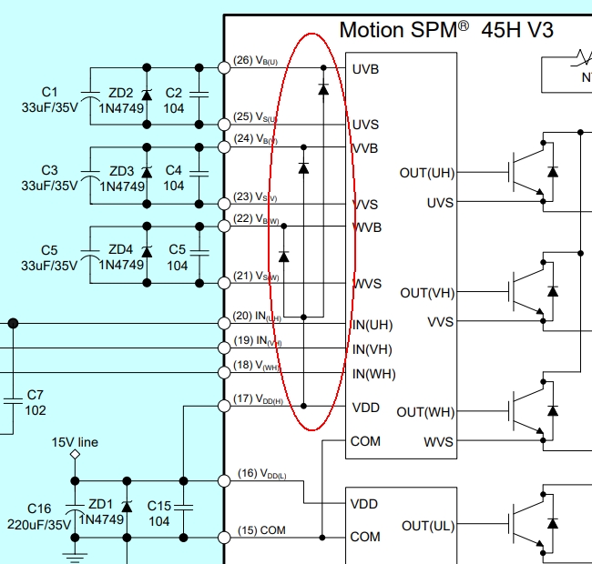
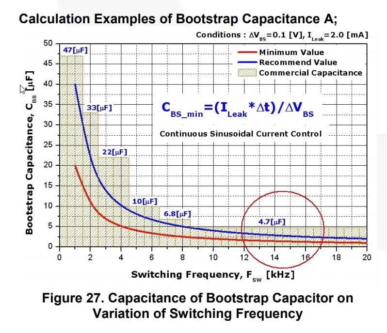
@Thanos I had it working with some capacitors on there and the 15v supply. But as far as I can tell it only works when the low side is switched on for some time periodically to charge the Bootstrap circuit. And if i want it to work while only the high side is on and the low side is off (for a long time) then i need to supply a external floating voltage to the 3 high side gate drivers for it to work.
@Valentine @Thanos look at page 20 (https://www.onsemi.com/pub/collateral/an-9084.pdf) at the oscilloscope shot that’s what I mean the low side charges the high side bootstrap voltage.