Can you share with us please what DVS diode you ended up using?
I ended up with this. https://www.mouser.dk/datasheet/2/115/ds40742-1509032.pdf
The 300 amp rating is forward pulses. 77amp peak current … Still good for steppers I believe.
So I just got an answer from the on semi technical support. I asked them if there where any problems to use the IGBT in a low voltage application like 24v and they say it would be no problem.
Thank you.
Steppers energy density is very low, they are slow and they are back-drivable.
Right, that’s why I’m aiming at 10A max. A non-back-drivable reducing transmission backed by a borderline gimbal, not quite a gimbal, not quite a power bldc but able to deliver fast enough speed @ 5kg/cm to drive the reducer. I’ve chosen a strain wave actuator at that point, which at 0.5n/m driving force and 1:50 would give me theoretically 25n/m which is about 2kg/meter @60rpm, enough to solve the problem on paper.
I’ve never seen such a powerful direct drive bldc motor commercially available, could you please give me a reference? The largest I’ve seen is 9kg/cm. 10Nm is 100kg/cm, that’s an order of magnitude difference.
Thanks,
Valentin
The hub motors from those Segway looking Chinese hoverboards has 10nm of torque, if you believe the odrive documentation,the most versions are 250/350w and 16kv(v/rpm) rated, if you buy them used for 50$ you get 2 motors and a decent lipo.
That’s ingenious, I could do that, thanks. Good pointer.
Mounting is a bit complicated because the motor wires come out in the middle of the shaft, but it’s doable, it’s on the odrive forum if I remember correctly.
For my application I opened the motor up and drilled a hole trough the backside where the bearing is so I could mount a encoder to the shaft, if you want I can see if I have some pictures.
I’ll buy one and tear it apart as a homework.
If you life in a city with more than 10 people, the guy in the next house over probably has one of these things he wants to get rid off on your local marketplace.
Damn, yesterday I literally saw one in the trash outside, I usually don’t dumpster dive but I should’ve. Kicking myself in the butt for that. Probably the battery went bad and they tossed it.
Don’t kick yourself for that, I take all the shit I see that looks interesting, and it’s also not a good habit.![]() , The really cheap ones you can get probably have a dead battery, but we don’t need that where we are going.
, The really cheap ones you can get probably have a dead battery, but we don’t need that where we are going.
Looks like you’ve gotten great tips already for that kind of motor spec, but in my case I was putting some numbers to paper. If the numbers come out super crazy, and you realize that we couldn’t get a 10Nm motor direct drive motor, then you’d have to consider gearing, or reduce your load mass etc etc. Had I selected a mass of 100kg we’d be talking about a 100Nm torque motor at 24V which would be even more interesting ![]()
However, I am personally interested in motors able to deliver about ~30Nm (gearless) at an operating voltage of up to 48V, and in my research a while ago I had found these guys: https://uumotor.en.alibaba.com/
but I have not yet ordered any of their motors so not sure if specs advertised reflect actual performance.
Thank you for your input.
I looked into them last year, these are bikes and scooters, the motors are powerful but massively heavy, come with a tyre pre-bolted to the motor and are appropriate only for people developing land devices where weight is not an issue. There is more than one company developing these, I think UU Motor are only the re-sellers. Not sure who is the original manufacturer. There are plenty of very high torque motors, think the ones that drive the Teslas and the Ford electric trucks, but they are an entirely different breed of animals. I was referring to motors that could be attached to joints.
Yes, gearing is definitely needed, especially for back-drivability concerns.
Hey @Valentine I got a little issue with my schematic, maybe you know this.
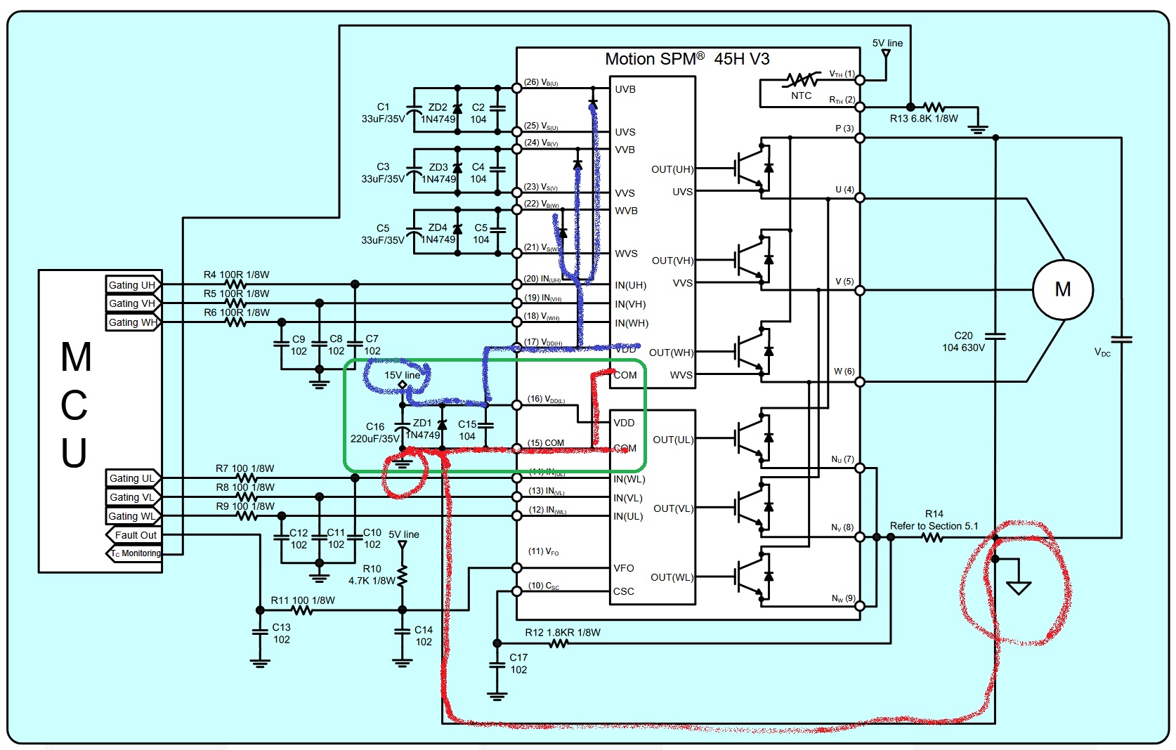
On the IGBT on pin 21 to 26 there is the Bootstrap circuit (this drives the low side mosfets), and as far as I can tell there would be issues with just using the typical application circuit because I can’t guarantee that the high side mosfets are switched on enough to charge the bootstrap circuit to supply the low side mosfets.
I just want to input a voltage (15v) into the 3 circuits. But I don’t get if the voltage has to be floating or connected to gnd, or if I have to use 3 separate isolated voltages to supply this.
Could you please look at the schematics in the user manual you sent here, it’s described in there, but I don’t quite get it.
Thanks for the help.
ill check later today
You don’t need that as the 15V is already supplied to these pins, please see the attached picture.
Also as a side note the GND->COM are electrically connected to the Power Ground (true ground) so you need to do that in your design, too.
Originally the true power ground is “real ground” however since you don’t have it just make sure its on a common rail.
@Valentine
Thanks I did wonder why I needed the 15v and the bootstrap circuit. So it’s 15v or the bootstrap circuitry on 21-26 i guess that makes sense now and reduces component count greatly. Im going to just put a external 15v psu on so I don’t have to generate the 15v on the PCB, and I can also generate the 3.3v for the esp32 from that nice and easy with a linear regulator.
Also another issues I came across is, somewhere it is mentioned that the thing operates on 5v CMOS but then somewhere different i read 3.3v/5v, i suppose the 3.3v output from the esp32 is going to work with this without a levelshifter.
Reading the documents, it seems the chip is 3.3v logic compatible as the high threshold voltage is 2.6v and low 0.8v. As far as the NTC thermistor is concerned you can re-scale to 3.3v logic based on the resistance table provided in the doc for temperature telemetry.
With the ntc i got no problem.
Anyway thanks for the help, i just ordered 3 igbts, two to use and one to blow up (lol).
I think with your help i got everything cleared up i didn’t understand.
I’m going to put a lot of headers and Testpoints on the PCB if something is not working right it’s easier to diagnose.
Just to report back, i got the IGBT module to work with simplefoc and esp32, only external components so far are 6 50ohm resistors and 3 random capacitors.