This is my first post here. I’m currently designing a BLDC controller for a hotplate magnetic stirrer and would love to get some constructive feedback on my schematic before I move forward.
Project Background
Application: A magnetic stirrer for a laboratory hotplate. The motor will have a magnet attached to its shaft to stir a magnetic bar in a beaker.
Load: I’m expecting a very low and relatively constant load.
MCU: Raspberry Pi RP2350. I’m aware of some community discussions about its ADC performance but simpleFOC does support in-line current sensing, eventho is not great, but I’m hoping it will be sufficient for this low-load application.
Driver: Texas Instruments DRV8350. My design is heavily based on the DRV8350 EVM reference board.
Motor: Maxon EC 90 flat Ø90 mm, brushless, 260 W, with Hall sensors part number 500266
Goal: To create a reliable, fully open-source controller under MIT license. The hotplate control circuitry is not included in this schematic (has not been developed yet).
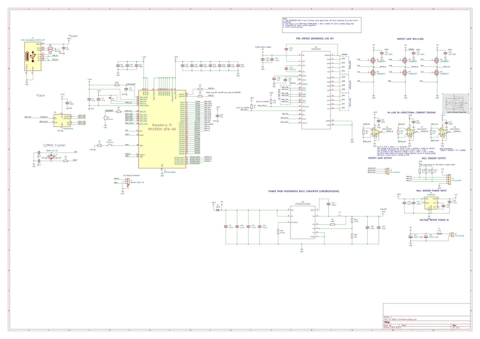
Schematic for Review
I’ve attached the PDF of the schematic below. The full KiCad project is public on my GitHub, but it’s a bit messy at the moment.
Using unidirectional current sensing on inline current sensing isn’t very useful as you cannot measure negative currents, and negative currents happen all the time when driving a brushless motor.
Also, you need a lower shunt resistance. The reason is because the motor you are using has a rated current of 7.06A and I am going to assume it is RMS as it doesn’t say clearly on the website. This means the peak current that will need to be measured (assuming waveform is a perfect sine wave) is 7.06A*sqrt(2)=9.98A. On top of this, add a 20% margin (otherwise control loop will have issues). So you need to be able to measure currents of around 12A. Since you are powering analog from 3.3V, if zero amps is half of that, then we have a maximum swing of 3.3V/2=1.65V. Assuming a gain of 50, the maximum voltage across the sense resistor is 1.65V/50=33mV. So the required resistance is 33mV/12A=2.75mΩ. Since this is the maximum resistance we can have without saturating the amplifier, we need to round it down to the nearest commonly available resistor value, which will probably be 2mΩ.
When calculating heat dissipated by the shunts you should use RMS current, and multiply by 3 as there are 3 shunts. So your heat dissipation for 2mΩ shunts is 7.06A^2 * 2mΩ * 3 = 0.299W, which is an acceptably low value.
Also if you are worried about stall currents, you should note that when using a properly tuned FOC controller, the motor will never experience the stall current. Stall currents usually happen when something has gone wrong, such as a software issue causing a half bridge to be stuck on. Additionally, integrated FET drivers (like the DRV8316C) tend to have better overcurrent and overtemperature protections than discrete FET drivers, which means it is less likely to accidentally blow something up in case of an issue. The reason is that for drivers like DRV835x family, although hardware overcurrent protection exists by sensing VDS across the MOSFETs, it is vulnerable to mistakes in calculating proper overcurrent protection thresholds (or forgetting to set it), and also vulnerable to issues with PCB layout causing inaccurate voltages to be sensed, due to parasitic resistance and inductance.
Integrated FET drivers have the disadvantage of not being good for high currents, and also having more power loss (DRV8316C MOSFET RDSon is 50 milliohm compared to less than 5 milliohm on many discrete MOSFETs). Personally after using it for a while I also think it switches too slow and dead time is too long. But it’s much easier to design a good PCB using an integrated FET driver as a beginner.
I’m looking forward to seeing your updated design. I’m currently also in the process of updating my motor driver PCB, and I will share it soon.
I’m not too familiar with how a magnetic stirrer works, but I have a feeling that a 260W motor with almost 1Nm of torque is going to be extremely overkill. It will probably be better to use a smaller motor.
You also have a driver rated for 80V when the motor nominal voltage is 30V. Unless you plan on overdriving the motor or are expecting a high power supply voltage, this also feels extremely overkill.
For low power applications, you might be better off using the DRV8316C driver chip as it’s a lot smaller and has integrated current sensing (although it is low side and not inline).
For your PCB:
I wouldn’t use a 10 milliohm shunt resistor, as that would cause large power losses and heat. Instead, I would recommend you to change it for a lower resistance around 1-3 milliohms, and compensate by increasing the gain of the amplifier.
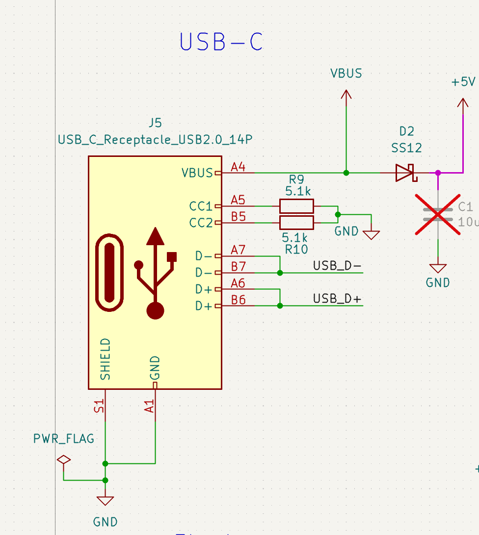
Also you have put diodes on the 3.3V rail, which will cause the 3.3V rail voltage to be lower than expected. The analog circuits connected will really hate this. I suggest removing the LDO from USB and letting the 3.3V rail only be powered when the main power is applied. The board cannot spin the motor with only USB power, so it’s quite pointless to implement a proper dual power input scheme.
The main buck regulator expects capacitors with high ESR on the output, but the input capacitors of the 12V buck regulator connected to the main buck regulator output have very low ESR, which has a small chance of causing issues. Some ways to solve it are to replace all the capacitors with electrolytics , or adding resistors to the input capacitors of the 12V buck. But personally I would just use the DRV8350S (without integrated buck) because the integrated buck is not very good, and add an external buck such as the LMR38020 or LM5164.
Hi @Andrew, many thanks for your review really appreciated it!
Yes, you are right. The reason we are using this motor because we got this lying around in our lab from a previous project, so we might as well use this.
The reason I chose high voltage is that I wanted flexibility. In the future, I may use it for a higher voltage motor or vice versa for a lower one. We will be using a fixed power supply.
At first, I was using the DRV8353RS with the integrated current sensing. I did comment/reply on a post by @runger about the support of RP2350 for simpleFOC. While low-side current sensing is not supported, the library does support in-line, albeit it still sucks. Having a dedicated gate would give flexibility.
Also, the reason for not using integrated FETs is that I worried about the stall current that goes through the IC from my not so inteligent action.
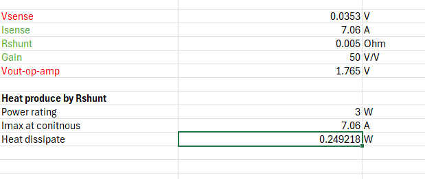
I have swapped this for 5 mOhm and use the same op-amp but with the gain of 50V/V. After some calculation and a lot of Google Gemini, I have calculated the total heat dissipation for the resistor at continuous current of 7.06A to be 0.25W (am using a 3W resistor), and the output of the op-amp is at 1.765V, it gives a headroom for double the op-amp reading. I configure the op-amp to read in unidirectional. Do correct me if I am wrong.
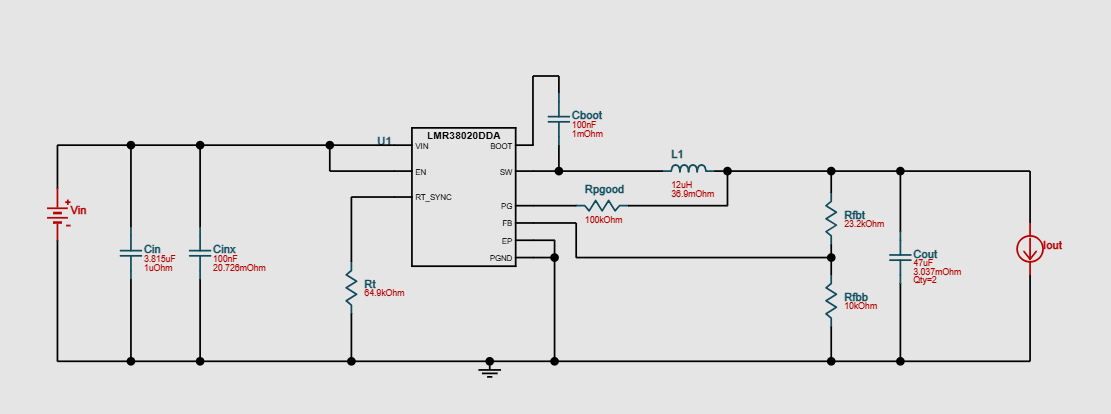
Thanks for the suggestion. I have swapped for a single LMR38020 and also placed a Schotky diode on the Vbus for protection. This is the schematic suggestion I got from using WEBENCH
Looks a lot better. But I still have a few concerns:
The diode idea is smart, but I see a small flaw. Diodes usually have a reverse leakage current which is usually quite small. But when the USB connector is disconnected for a long time, and a high voltage power supply is applied to VM, it will slowly charge up the 10uF input capacitor on the USB port. Now it will be up to the leakage currents between the components which determines the final voltage which ends up on the 10uF capacitor, but if the capacitor is high quality (and has low leakage) it may end up being charged up very close to VM voltage, because there seems to be nothing else connected to VM which might clamp the voltage. When you go and plug in your computer in this situation it might not end very well…
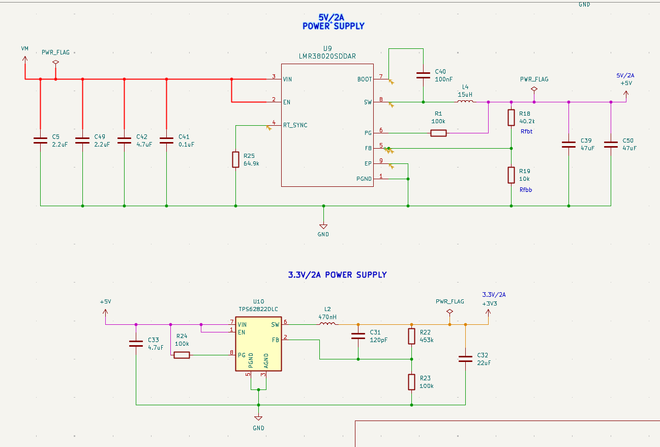
Also, it would be better to change the buck regulator to output 5V, and use another 3.3V buck regulator (such as TPS62826) to generate the 3.3V. This way it will be more efficient and can output more power in total, because high input voltage buck converters are not great for producing low output voltages.
For a high voltage design needing to handle 80V input, it makes a lot of sense to generate the VM voltage for the DRV8353 using the buck set to 12V, then use another low voltage buck to generate 3.3V and 5V. This will save significant power as the DRV8353 will use a LDO internally if you supply VM with a higher voltage. But if low power isn’t a concern, or you want a simpler / cheaper design, then you can keep the current single supply setup.
You shouldn’t need extra electrolytic capacitors for the buck converter input as your main electrolytic capacitors should already work fine. A few ceramics should be enough.
Charge pumps are great, but only when the output voltage you want is an exact fraction or exact multiple of the input voltage. If this condition is met, charge pumps have a very high efficiency and can usually beat inductor based regulators, hence why they are popular in smartphone fast charging circuits. But trying to generate 5V from 3.3V using a charge pump isn’t a great idea.
In my design I use a charge pump to generate 10V from 5V (exactly double) so it gives me around 90% efficiency, but in your case the theoretical efficiency is limited to 75% and practically will be even lower.
I took your advice, and I have implemented a 2-buck regulator. VM to 5V/2A to 3V/2A. There’s another buck regulator that converts VM (Supposedly 30V) to 12V/1A. On the final open-source design, I might remove this.
Hello @syauqi-alias could you please let me know that whether your circuit with 5V to 3.3V gneration did worked with TP62826 are you getting stable output of 3.3V ? any issues you’ve noticed ?