Deng FOC Board - Easy to use!

Hi Folks,

For those of you who want to quickly get familiar with SimpleFOC using low power motors (gimbal), I recommend trying this board from Aliexpress:

It includes 2 sets of AS5600 I2C mag sensors, which are adequate for simple projects or getting familiar with position sensors.

I was able to successfully use all control modes with it, including FOC current current (true torque control!). In the past, I had some trouble getting current mode to work, mostly due to not knowing what values to set for the q and d PI gains.

The example Arduino files located here work great for small gimbal motors: Deng-s-foc-controller/Dengs FOC V3.0/Dengs FOC V3.0 测试例程(支持库SimpleFOC 2.2.1) at master · ToanTech/Deng-s-foc-controller · GitHub

Cheers!
Ben

Hi Ben,

I just received my Deng FOC board. Shame I did not see your post before, it took me some time to find the sample code, the only way of knowing the pins to allocate etc.

I agree the board seems to do everything that simpleFOC offers.

As I go through the examples I reached the dengFOC Current test example. This one crashes on me. Does it work for you?

Regards,

Carl

For other readers this is the Feng FOC 3.0 driven by an ESP32 development board lolin32 lite on the bottom.

Here is the code.

//Current detection test routine Test hardware:FOC V3.0
#include <SimpleFOC.h>

// Current Detection
// Sampling resistor value Gain ADC pin
// check if your board has R010 (0.01 ohm resistor) or R006 (0.006 mOhm resistor
InlineCurrentSense current_sense0 = InlineCurrentSense(0.006, 50, 39, 36, _NC);

void setup() {

Serial.begin(115200);
delay(1000);
Serial.println(“Current sense ready.”);
delay(1000);
// Current Detection

current_sense0.init();
//current_sense0.gain_b *= -1;
}

void loop() {
Serial.println(“Current sense ready.”);

PhaseCurrent_s currents0 = current_sense0.getPhaseCurrents();
float current_magnitude0 = current_sense0.getDCCurrent();
Serial.print(currents0.a1000); // milli Amps
Serial.print(“\t”);
Serial.print(currents0.b
1000); // milli Amps
Serial.print(“\t”);
Serial.print(currents0.c1000); // milli Amps
Serial.print(“\t”);
Serial.println(current_magnitude0
1000); // milli Amps
Serial.println();
}

And here is the crash

Rebooting…
Current sense ready.
Guru Meditation Error: Core 1 panic’ed (LoadProhibited). Exception was unhandled.

Core 1 register dump:
PC : 0x400d1d1b PS : 0x00060830 A0 : 0x800d11e6 A1 : 0x3ffb27d0
A2 : 0x3ffc1180 A3 : 0x00000014 A4 : 0x0800001c A5 : 0x00000003
A6 : 0x00000001 A7 : 0x00000000 A8 : 0x00000000 A9 : 0x3ffb27b0
A10 : 0x000003e8 A11 : 0x3ffbef48 A12 : 0x00000000 A13 : 0xffffcfc7
A14 : 0x3ffb7e50 A15 : 0x00000000 SAR : 0x00000003 EXCCAUSE: 0x0000001c
EXCVADDR: 0x00000020 LBEG : 0x4008646d LEND : 0x4008647d LCOUNT : 0xfffffffa

Backtrace:0x400d1d18:0x3ffb27d00x400d11e3:0x3ffb27f0 0x400d323a:0x3ffb2820

ELF file SHA256: 0000000000000000

By the way, it crashes on current_sense0.init();

Hey Carl,
This is a bug of the simplefoc I think. It is fixed in the dev branch if you are interested in changing.
If not, you’ll need to create a dummy BLDCDriver instance do not even need to init it. Just link it to the current sense, before you call the current sense init. current_sense.linkDriver(&driver);

Awesome fast reply, thanks that fixed it. For other viewers below is the working code.
Now to go and find these currents in simpleFOCStudio!!

Regards,

Carl

//Current detection test routine Test hardware:FOC V3.0

#include <SimpleFOC.h>

//Dummy BLDC
// BLDC motor & driver instance
BLDCMotor motor = BLDCMotor(8);
BLDCDriver3PWM driver = BLDCDriver3PWM(32,33,25,22);

// Current Detection
// Sampling resistor value Gain ADC pin
// check if your board has R010 (0.01 ohm resistor) or R006 (0.006 mOhm resistor
InlineCurrentSense current_sense0 = InlineCurrentSense(0.006, 50, 39, 36, _NC);

void setup() {

Serial.begin(115200);
delay(1000);
// Current Detection
current_sense0.linkDriver(&driver);
current_sense0.init();
current_sense0.gain_b *= -1;
Serial.println(“Current sense setup complete.”);
delay(1000);
}

void loop() {

PhaseCurrent_s currents0 = current_sense0.getPhaseCurrents();
float current_magnitude0 = current_sense0.getDCCurrent();

Serial.print(currents0.a1000); // milli Amps
Serial.print(“\t”);
Serial.print(currents0.b
1000); // milli Amps
Serial.print(“\t”);
Serial.println(current_magnitude0*1000); // milli Amps
}

@Antun_Skuric Do the fixes in the dev branch address the issue where using current sensing prevented the use of analogRead()?

Hey @wrcman555,

No, this we did not address yet and might not so soon.

If your analogRead does not work with current sensing you can use adcRead which is a more efficient version of the analog read.

You might have to include in addition to simplefoc.h:

#include "current_sensing/hardware_specific/esp32/esp32_driver.h"

@Antun_Skuric Thanks! I remember you telling me that. It works well!

Inline current sensing worked fine for me out of the box on the dev release and I could go to FOC current control on torque.

@Carl Same here! I am using the 2 exposed esp pins (I0 and I1) to read values from an external dc current sensor as well as a potentiometer. I had to use adcRead() instead of analogRead().

Hello, I am not sure if I am allowed to post it here. I need some help to complete a simple project using the Deng FOC board for some monetary compensation. Is there any other way to contact forum member?

You can send direct messages :slight_smile:

Glad to help, send me a message

Hey guys… i dont know is this thread is still active but i have a MKS Dual FOC plus V3.2 + ESP32 that i got from Alibaba
I am planning to drive a simple gimbal BLDC and i have a few questions

  1. after attaching the esp32 to the driver board will i still need to install any kind of firmware on the driver or is it just SimpleFOC on ESP32 is enough.
  2. i learn better by looking at examples and documentation and i cant seem to find any to so i am stumped at coding this thing ( If there is any code for this MKD dual driver plus esp32 board.)

Hi,

  1. all you need to do is run the Arduino sketch on the esp32. There is no extra firmware for the board
  2. You can find code examples and some documentation on their GitHub:MKS-DUALFOC/Test Code at main · makerbase-motor/MKS-DUALFOC · GitHub

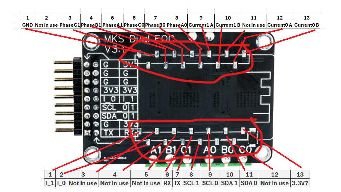
For anyone trying to use current sensing with MKS-DUALFOC with esp32 and also could not find documentation anywhere on how to use this board (In post above there is 0 direction/help on header pinout which I found annoying that they then pointed to another piece of hardware to buy on aliexpress instead of one in the “supported hardware” I already bought that was listed in the simpleFOC docs but I can complain about that another time) here is the pinout you need. My board from elixpress included headers to solder to pads in picture. Takes a bit of skill with smaller soldering iron.

Pinout numbering I listed here can be found on schematic on left hand side here: MKS-DUALFOC/Hardware/MKS DUAL FOC V3.1 PLUS_001 Schematic.pdf at main · makerbase-motor/MKS-DUALFOC · GitHub

Just connect common ground between esp32 on MKS board powered by 12v+ power supply and pwm pins for bldc motor go to phaseA,B,C and Current0 A/B go to GPIO ADC pins (pins have to have adc functionality to read analog voltage from MKS board) on esp32 board. You then have to use Lowsidesense from simpleFOC library with adc pins you selected and bababooey

BLDCMotor motor = BLDCMotor(11);

BLDCDriver3PWM driver = BLDCDriver3PWM(25, 26, 27);

LowsideCurrentSense current_sense = LowsideCurrentSense(0.01, 50.0, 36, 39, _NC);

On my esspresif esp32 dev module pins 36, 39 are listed as VN and VP respectively.

25, 26, 27 are my pwm “phase” wires to MKS board.

Hope this helps anyone who runs into same problem

I made mistake in earlier code here. I guess mks v3.2 dual foc board (rip off ones from aliexpress) use InlineCurrentSense. Below is code for dual 2804 gimbal motor holding 0 position with an idle timeout.

// Using lib_deps = askuric/Simple FOC@^2.4.0
#include <Arduino.h>
#include <SimpleFOC.h>
#include <Wire.h>

// ======================= Hardware pins =======================
// Motor 0 (I2C port 0)
constexpr int M0_I2C_SDA = 18;
constexpr int M0_I2C_SCL = 19;
constexpr int M0_PWM_A   = 33;
constexpr int M0_PWM_B   = 25;
constexpr int M0_PWM_C   = 26;
constexpr int M0_CS_A    = 39;
constexpr int M0_CS_B    = 36;
// Motor 1 (I2C port 1)
constexpr int M1_I2C_SDA = 22;
constexpr int M1_I2C_SCL = 23;
constexpr int M1_PWM_A   = 27;
constexpr int M1_PWM_B   = 14;
constexpr int M1_PWM_C   = 12;
constexpr int M1_CS_A    = 32;
constexpr int M1_CS_B    = 35;

// ======================= Motor specs & limits =======================
// These values are for 2804 gimbal motor
constexpr int   POLE_PAIRS = 7;
constexpr float PHASE_RES  = 0.25f;   // [Ohm]
constexpr float KV         = 360.0f;  // [rpm/V]
constexpr int   VOLT_SUPPLY = 24;     // power supply [V]
constexpr float VOLT_LIMIT  = 4.5f;   // [V]
constexpr float VOLT_ALIGN  = 2.0f;   // sensor/motor align [V]
constexpr float CURR_LIMIT  = 2.5f;   // [A]
constexpr float VEL_LIMIT   = 3.28f;  // [rad/s]

// ======================= Control mode =======================
const TorqueControlType TORQUE_MODE = TorqueControlType::foc_current;
const MotionControlType MOTION_MODE = MotionControlType::angle;
const FOCModulationType FOC_MODE    = FOCModulationType::SpaceVectorPWM;

// ======================= PID / filter tuning =======================
constexpr float CUR_PID_Q_P = 2.0f, CUR_PID_Q_I = 50.0f;
constexpr float CUR_PID_D_P = 2.0f, CUR_PID_D_I = 50.0f;
constexpr float CUR_LPF_TF  = 0.005f;
// Quiet, damped profile (no velocity-D noise amplification).
constexpr float VEL_PID_P = 0.075f, VEL_PID_I = 0.25f, VEL_PID_D = 0.0f;
constexpr float ANG_P     = 10.0f,  ANG_I = 0.0f,    ANG_D = 0.0f;
constexpr float VEL_LPF_TF = 0.005f;
constexpr float VEL_RAMP   = 80.0f;

// ======================= Demo behavior =======================
constexpr float POSITION_DEADBAND = 0.05f; // ~3 deg; stop hunting on encoder noise at rest
constexpr int   IDLE_TIMEOUT_MS   = 1000;  // release motor after this long settled
constexpr int   PRINT_PERIOD_MS   = 1000;  // print cadence [ms]

// ======================= Hardware objects =======================
TwoWire          I2Cone(0);
MagneticSensorI2C sensor0(AS5600_I2C);
BLDCDriver3PWM    driver0(M0_PWM_A, M0_PWM_B, M0_PWM_C);
InlineCurrentSense current0(0.01f, 50.0f, M0_CS_A, M0_CS_B, NOT_SET);
BLDCMotor         motor0(POLE_PAIRS, PHASE_RES, KV);

TwoWire          I2Ctwo(1);
MagneticSensorI2C sensor1(AS5600_I2C);
BLDCDriver3PWM    driver1(M1_PWM_A, M1_PWM_B, M1_PWM_C);
InlineCurrentSense current1(0.01f, 50.0f, M1_CS_A, M1_CS_B, NOT_SET);
BLDCMotor         motor1(POLE_PAIRS, PHASE_RES, KV);

// ======================= Per-motor config + init (shared) =======================
// Both motors are configured identically except their I2C bus pins and the
// zero electric angle, so a single helper drives both setups.
void initMotor(BLDCMotor& motor, BLDCDriver3PWM& driver, MagneticSensorI2C& sensor,
              InlineCurrentSense& cs, TwoWire& i2c, int i2cSDA, int i2cSCL,
              float zeroElectricAngle) {
  i2c.begin(i2cSDA, i2cSCL, 400000UL);
  sensor.init(&i2c);

  driver.voltage_power_supply = VOLT_SUPPLY;
  driver.init();

  motor.linkSensor(&sensor);
  motor.linkDriver(&driver);
  cs.skip_align = false;
  cs.linkDriver(&driver);
  cs.init();
  motor.linkCurrentSense(&cs);

  motor.voltage_limit        = VOLT_LIMIT;
  motor.voltage_sensor_align = VOLT_ALIGN;
  motor.current_limit        = CURR_LIMIT;
  motor.velocity_limit       = VEL_LIMIT;

  motor.PID_current_q.P = CUR_PID_Q_P;
  motor.PID_current_q.I = CUR_PID_Q_I;
  motor.PID_current_d.P = CUR_PID_D_P;
  motor.PID_current_d.I = CUR_PID_D_I;
  motor.LPF_current_q.Tf = CUR_LPF_TF;
  motor.LPF_current_d.Tf = CUR_LPF_TF;

  motor.torque_controller = TORQUE_MODE;
  motor.controller        = MOTION_MODE;
  motor.foc_modulation    = FOC_MODE;

  motor.PID_velocity.P = VEL_PID_P;
  motor.PID_velocity.I = VEL_PID_I;
  motor.PID_velocity.D = VEL_PID_D;
  motor.P_angle.P = ANG_P;
  motor.P_angle.I = ANG_I;
  motor.P_angle.D = ANG_D;
  motor.LPF_velocity.Tf       = VEL_LPF_TF;
  motor.PID_velocity.output_ramp = VEL_RAMP;

  // Uncomment once you have made sure values in setup() are set for your configuration
  // motor.sensor_direction    = Direction::CCW;
  // motor.zero_electric_angle = zeroElectricAngle;

  motor.init();
  motor.initFOC();
}

// ======================= Per-loop FOC step + idle auto-disable =======================
void runMotor(BLDCMotor& motor, unsigned long& idleTimer, float target) {
  // Still moving? Reset the idle timer so an active motor stays enabled.
  if (fabsf(motor.shaftAngle() - target) > POSITION_DEADBAND) {
    idleTimer = millis();
  }
  motor.move(target);
  motor.loopFOC();
  // Release once settled for IDLE_TIMEOUT_MS; re-enable if released early.
  if (millis() > idleTimer + IDLE_TIMEOUT_MS) {
    motor.disable();
  } else if (!motor.enabled) {
    motor.enable();
  }
}

// ======================= Setup =======================
void setup() {
  Serial.begin(115200);
  delay(200);
  SimpleFOCDebug::enable(&Serial);

  initMotor(motor0, driver0, sensor0, current0, I2Cone, M0_I2C_SDA, M0_I2C_SCL, 1.25f);
  initMotor(motor1, driver1, sensor1, current1, I2Ctwo, M1_I2C_SDA, M1_I2C_SCL, 4.15f);

  motor0.enable();
  motor1.enable();
}

// ======================= Loop =======================
unsigned long motor0_idle = 0;
unsigned long motor1_idle = 0;

void loop() {
  static unsigned long lastPrint = 0;
  if (millis() - lastPrint >= PRINT_PERIOD_MS) {
    lastPrint = millis();
    Serial.printf("M0: %6.2f A / %6.2f A | M1: %6.2f A / %6.2f A\n",
                  motor0.current.d, motor0.current.q,
                  motor1.current.d, motor1.current.q);
  }
  runMotor(motor0, motor0_idle, 0.0f);
  runMotor(motor1, motor1_idle, 0.0f);
}