This seems interesting.
I have had some experience with this board few years ago, before simplefoc era
And I remember it being frustrating because the board has implemented some ramping algorithms or something like that, and by removing the IC I was left with a lot of unknowns
The 6pwm mode has dead-time implemented:
I’ve called it a dead-zone. It is essentially the same thing, just I’ve made a choice for it to be a percentage of the duty cycle as opposed to the time delay. But the mapping in between them is easy.
@Owen_Williams will be able to give you much more info about the hoverboard motors, he has become a real expert!
I’ve got a couple of those boards but haven’t attempted to desolder. I was hoping that the chip would be reprogrammable but I don’t think it can. I’d be interested to hear how you get on!
At the moment I’m using 2x stm32g431 discovery kit for drones to drive two hoverboard motors. They are a little bit underpowered for hoverboard motors and hard to solder but are a reasonable match. I’m looking for a better dual motor solution and might have to resort to printing my own board.
Hi, I was impatient and destroyed the IC pads, but managed to solder the wires directly to IR2101 pins.
I have a few Arduinos laying around and thought to test the idea but I’m not sure about the code - I would like to at least avoid frying the board on the first try.
The code seems fine. Just make sure to respect high/low pair pins HIGH/LOW 5/6, 9/10, 3/11
Also, I would limit the voltage even more to 1V maybe, start small
Thanks a bunch. I have no equipment
I tested from ATX PSU instead of batteries and seems to work intermittently - I see the “misbehavior” Owen mentions in his tuning video but I’m guessing the reason is not the same since sometimes the PSU shuts down https://www.youtube.com/watch?v=ufMs83Y3sXg
That might be caused by my soldering “skills”
I’ll have some more spare time during the weekend to try to make this work correctly.
Lowered voltage to 3 and velocity to 1 and it’s turning smoothly in openloop wit a current draw of less than .5 amps - shutting down seems to be a PSU issue, it’s dying.
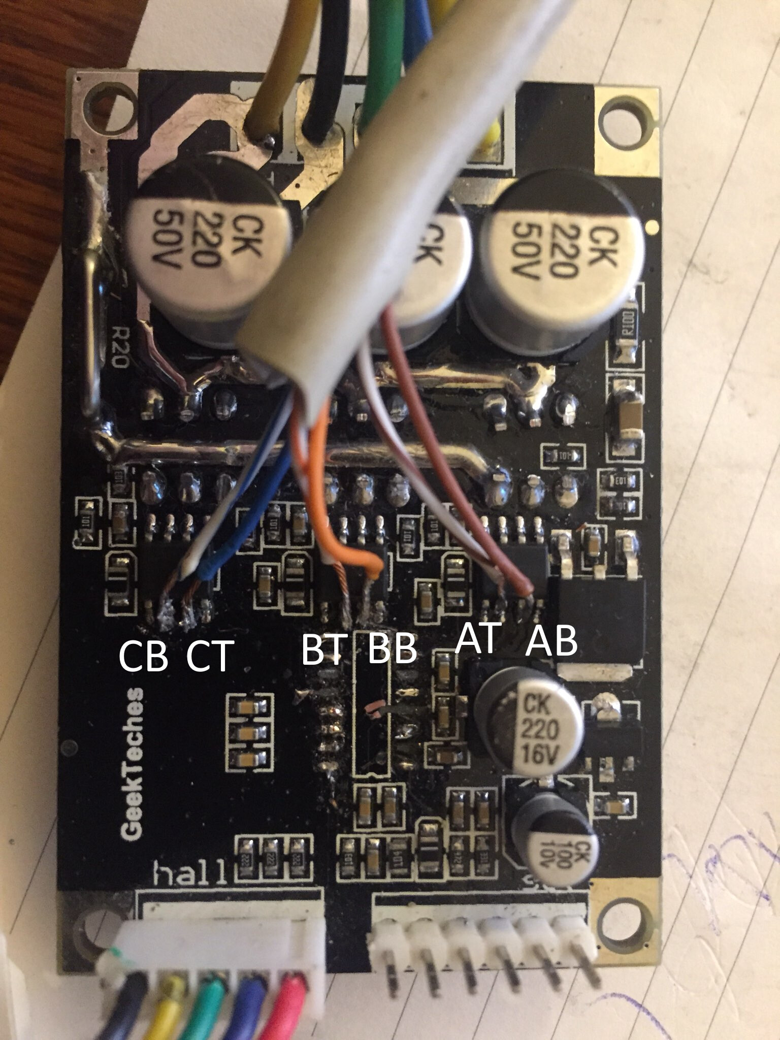
I bumped into JY01 datasheet in English (the removed IC - probably translated), and there’s not much I can draw but I can share the pins diagram and schematics (can’t upload PDF here) for now.
I was planning on wiring it to the JY01 IC pads, but I ended soldering them directly to IR2101 pins
.
AT/AB - pin 5/6
BT/BB - 9/10
CT/CB - 3/13 (the markings for this pair is wrong on the photo)
It’s easier to cleanly remove the IC and solder on pads, but I missed that chance. There are no components between JY01 IS and the mosfet drivers, so it’s basicaly the same.
I have hooked up the hall sensors directly to the Arduino (pro mini) using the internal pullup and software interrupts. Still running it in an open loop, and the sensors output values that make sense.
As I mentioned earlier, I have no equipment to precisely test anything, but my multimeter doesn’t ever seem to register more than 3.8-3.9v on the hall sensor, and sometimes it gives barely 2,5V, so I guess that pull-up is a way to go.
I’ll redo the soldering when I get my hands on copper enameled wire, connectors and some mounting for the connector to replace the UTP cable and make this usable for me.
I’ll post a video of this setup working when I get the chance, but I warn you - it’s ugly
Open-loop is pulling around 2 amps at 12V. The mosfets are getting warm after a few minutes which might be a shoot-through issue due to the wrong dead-zone setting. I’ll have to test different values and take temp readings on mosfets as I have no scope to debug this properly.
Voltage control for the same settings is pulling 0.2 - 0.3 amps but reached almost 1.5 amps when I applied mechanical load to the wheel. I could not hold the wheel long enough to see if it will pump up the temp on mosfets as it did in open loop, but I’ll get to that as well.
I’d say that this works reasonably well for now, and is dirt cheap.
Another cheap approach could be to use BTS7960B drivers, and that wouldn’t require any soldering skills - 3 boards could drive 2 motors, and are rated at 42 amps, 5-27V, but I don’t have them.
Very cool!
I’m happy you found a solution and that it works
BTS7960B are great ics and they are very similar to
IFX007T. Very powerful and simple to handle.
I’m actually considering both for the higher power version of the simplefoc shield.
When starting, I feel that the current is large. For a high-power motor, the starting current will almost reach 90% of the current limit value. And then leveled off. The position closed-loop mode is normal, and the speed closed-loop mode, when the speed exceeds 90rpm, the current will increase to the current limit value, and the bts7960 will be very hot. Of course, maybe I use a big motor, which is the steering motor of the car. For ordinary small motors, there is no problem, and there is no time to test the torque mode. It is suggested to add current detection to the library.