I am looking for some advice for a robotic project I am trying to build. I need some hardware and software to control some DC brushless motors.
There are two types of motors. 2 of one kind and 4 of another. Both types are DC brushless type motors.
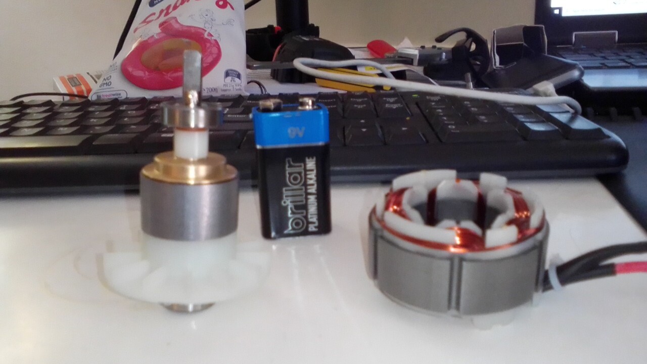
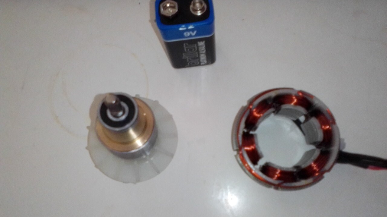
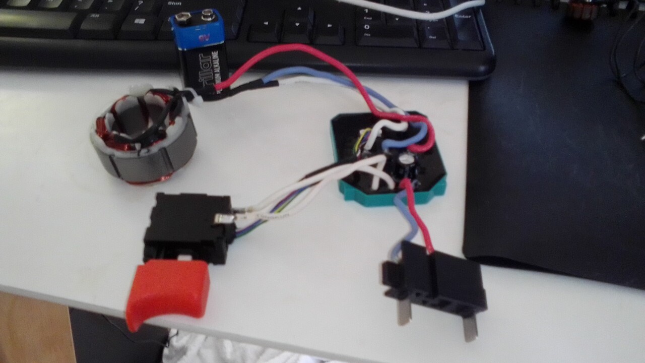
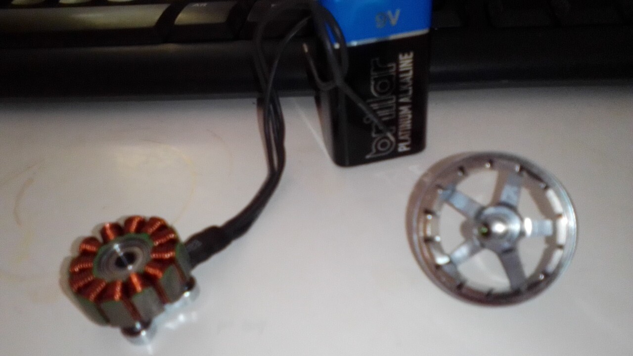
The first 2 come from power tools of the same kind and have ajustable speed but no reverse. There are three pictures with a 9V battery so you can see the size. The stator has 6 coils of wire and the armature is a cylindrical laminated magnet. The motor runs a 20V li Ion battery. The copper winding wire size is approx 0.75mm. I could not find any other spec on these two motors but hey are pretty powerful as you cannot stop them with your hand on even half power. I will just trash the controllers if they are no good for the job.
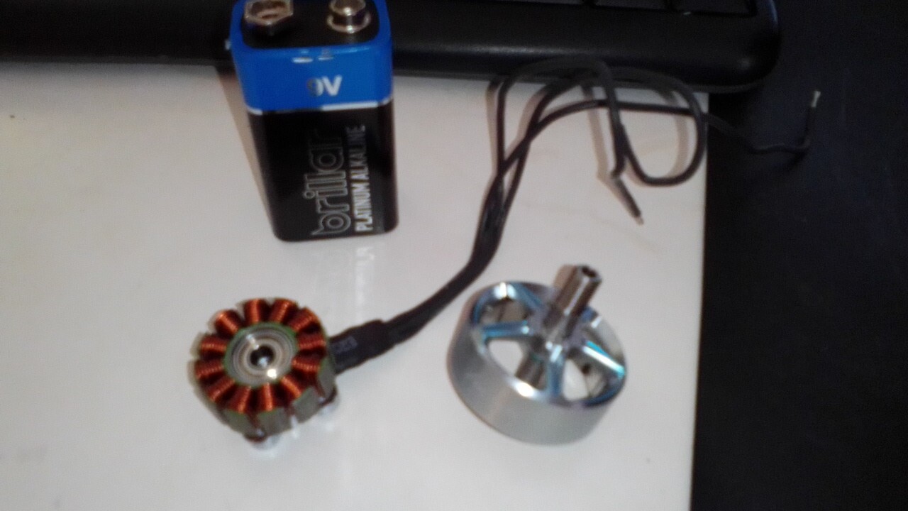
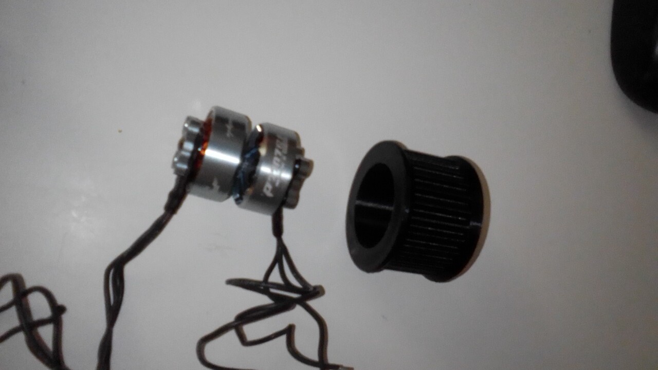
The other four motors are drone motors and they are of the type 12N14P. (12 coils and 14 magnets.)
Specs:
Brand Name: T-Motor
Model: Pacer V2 P2207
Item Name: 1950KV 6S Brushless Motor
KV: / 1950KV
Configuration: 12N14P
Shaft Dimeter: 5mm
Lead: 20AWG, 150mm
Dimension: 28.1x31mm
Weight: 28.4g ( exclu cable); 31.7g ( include cable)
Input Voltage 6S
Idle Current (10V)1.1A
Internal Resistance 56.5mΩ|Idle Current (10V)1.1A
Peak Current ( 60S 39.3A
Max. Power ( 60S) 878W
Bought here:
I am no expert on this subject but I have enough knowlegde to put it all together if I can find out what hardware/sofware combination I require. I have virtuall no budget so the cheaper the better :). This FOC I found intrugeing as it seem that the velocity mode may do the trick.
This is what I need to do. Please don’t ask me to explain this project bc I do not know all about it. I just have to control these motors in the following way.
The 2 powertool motors must go backwards and forwards with their RPM sycronized as accurately as possible. The RPM range is approx 0 - 2000 RPM max. The torque must be as high as possible as the loads changes mutiple time per revolution. The load is not known with any accuracy but is much less than the power drill it came from. The motors will run in opposite directions at the same time.
The four drone motors must go backward and forward and all four must have their RPM as acurately sycronized as the drill motors above. The RPM range is 0-4000 RPM Max. The torque must be as high as possible as the loads changes mutiple time per revolution. The load is also not yet known but probably less than the propellers they normally drive. Two of the four motors will run forwards and two in reverse all at the same time. These motors will be used in pairs to run 2 toothed belts … like 2 mini conveyors in sync with each other.
If I can get sugestions on the hardware/software to control these motors as above I guess I will need some position control like hall sensors. The space is very limited so I cannot use shaft positioning for drone motors and the position impulse will have to come from the belts. In the case of the drill motors there is some space for shaft positioning sensors.
The robot will not be flying FYI. The drill motor pics are the single magnet one and the drone motor is the other type with the bell armature removed.
Would be so grateful if some one can advise me. Thank you all in advance
Note: the 2nd and 3rd links aren’t publicly accessible…
It sounds like an interesting project. The more details you can give, the better people will be able to help you. For example, I find interesting why the motors RPM need to be synchronized?
For FOC control you will need an accurate position sensor on each motor. Magnetic sensors are a good option, as are encoders, but in each case you’ll need a little bit of space.
I think FOC control, once properly tuned, will be a good way to keep the speed constant under changing loads.
The power tool motors look like they have 3 phases (white cable kind of hard to see) and the T-Motor motors are quite standard. So in both cases you will need a 3-phase brushless motor driver for each motor.
You can measure the resistance of the power tool motor phases by measuring the value between any 2 of the phases. That will give you an idea of the current that will flow, and hence what strength of driver you need.
Thank you so much fotr your interest. Sorry so late with a reply. I am trying to get the resitance measurements for the drill motors and will get back later today. Again thank you :)))
The reason the sync is necessary is bc it’s a similar situtation to those helopcopter with two big blades that have to avoid collision bc they overlap. It can be done with physical gears but we are trying to reduce the number of parts and friction etc. It is not as critical as it would be in a helicopter as long as the sync can be re-established on a consistent basis.
So
the two drill motors must be synced together for one part of the device.
the four drone motors must be synced together for another part of the device.
the two devices need to linked via an arduino?? set up so that they can be adjusted to run at an adjustable RPM ratio to one another.
The Drill motors have speed controllers that may be able to be controlled by the arduino??
It is an interesting robotic device and I appreciate any help. Thank you all :))
From a purely theory point of view this isn’t exactly the “phase resistance”, more like the “phase 2 phase resistance value”, and its relation to phase resistance (theoretical) will depend on wether the motor is wye or delta wound, I think.
In practice, you just want an approximate value to know if this motor is high ohm (probably not) or low ohm (probably) so that you can set appropriate voltage limits in your driver.
E.g. a 10Ω motor at 10V will consume 1A, probably fine, while a 0.01Ω motor at 10V will consume 1000A, and burn up your controller.
While not impossible, this sounds difficult… what are the consequences of going out of sync? Will there be physical damage?
A mechanical linkage between the synced motors will guarantee they stay in sync. Doing it in software will be a bit more of a challenge. Lets assume you use magnetic sensors, so you have absolute positioning of the motor shaft. So in theory you can do a calibration step where you correlate the positions of these two sensors so you know what offset to each other you want to have them in sync.
So then you have to control each motor to maintain this offset while also controlling the speed. In theory SimpleFOC, with magnetic sensor will let you control positions or velocities quite precisely. But each driver and each motor will be a tiny bit different, so the motors will become out of sync if you don’t correct their positions.
Two ideas:
Use velocity mode and continuously exchange information between the drivers to adjust the speeds to maintain the desired offset.
Use position mode and a “central heartbeat” which updates the positions of all the motors in step, sending new positions quickly enough to maintain continuous motion.
Yes, this looks feasible from the pictures, but you won’t get FOC control in this way (and can’t use SimpleFOC), because you would not be controlling the motor phases directly. They would be under the control of the speed controller, and the Arduino would just be switching that on/off.
Thank you again for you enlightened interest. Yes we did make a mechanical one but is is very heavy and clumsy even with light weight gears etc. It is not critical (no damage will be done) if all does not sync perfectly. Since many times it will runs at a constant speed the Arduino could adjust in a fairy consistent way without too many surprizes at this stage. The effect of the changing load can be anticipated over the operational range of speeds. The RPM would not exceed 2000rpm with this one anyway. If, like you mention, a central heartbeat to co-ordinate it all may be a good idea but right now I have no clue how we would do this.
I have experience with programming and some basic electronics and can make most things work with a bit of guidence. It will most probably be interesting to the community as well.
Operating the device with lets say one speed controller per motor manually with potentiometers is possible but much finer control is needed and this is why I found this Simple FOC very interesting. I have got the general idea of it all and will study it further but am pressed somewhat by time and learn much better when my hands are on the things that will make it all work.
I will measure to coil resistence in the drill motors and make a few diagrams of the device so you can have a better idea of what needs to be done.
I will post again later today from Australia. Thanks for you interest.
I did isolate two coils in the drill motors and they show virtually no resistence. I guess if it was a high resistence motor it would have given a reading. These motors run off 20v li ion batteries and they know for their high torque output. I have run 20V DC through them with no load and they draw about 11amps.
The basic drawing looks like a conveyor belt contraption. The green dot represents a load attached to the belt. The belt is driven by the drone motors that are inside the red containers at each end of the belt. This belt just goes round and round the two motors as you can see in the pictures above.
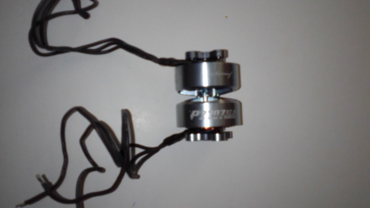
I tried to find the smallest diameter motor with a high torque output and I got 4 motors which I will arrange face to face and then slide into the belt drive pulley as you see in the picture. I will have to line up the poles and the magnets when I join then on a common axel. So there is one double motor of these at each end of the belt. I will join the the leads so they will run as if they were one motor on each end. Even if one is a bit slow they shd take up the slack overall and run as one motor.
So a belt that carries a load driven at both ends. Need these two ends to run at the same speed even if the load changes or adjust quickly.
The blue disc this conveyor is attaches to is run by one of the Drill motors. If you call this disc system 1 and the conveyor system two, then there is a ratio that can be adjusted so that an ideal set up will make it all work properly.
All I really need to know is what boards do I need to get and how many of each and I can get the show going. The drill motors will also need to be controlled bu Simple FOC as the controllers are not linear … as the switch is depressed it speeds up in steps so I cant use those.
Sorry this is as plain as mud but just tell me if what you need to adbvise me.
Ok, I get the idea of where you are going… I’m not knowledgable in mechanics / mechatronics, so I can’t really comment on the feasibility or efficiency of this kind of setup, but my gut feeling is why not? 2 motors should be stronger than one, and belts are a bit flexy and smooth everything out… so give it a go!
That all seems reasonable, but it does mean you’ll need a powerful motor driver. @David_Gonzalez Dagor board should handle it if available, and there are also some boards on AliExpress which claim to handle 36V/20A… (search for simplefoc). Haven’t tried those though.