Has anyone tried using this driver board with a stepper? I’m curious if the current sensing will work with the library. Looks like you have to read a voltage on one of the pins to get the current…
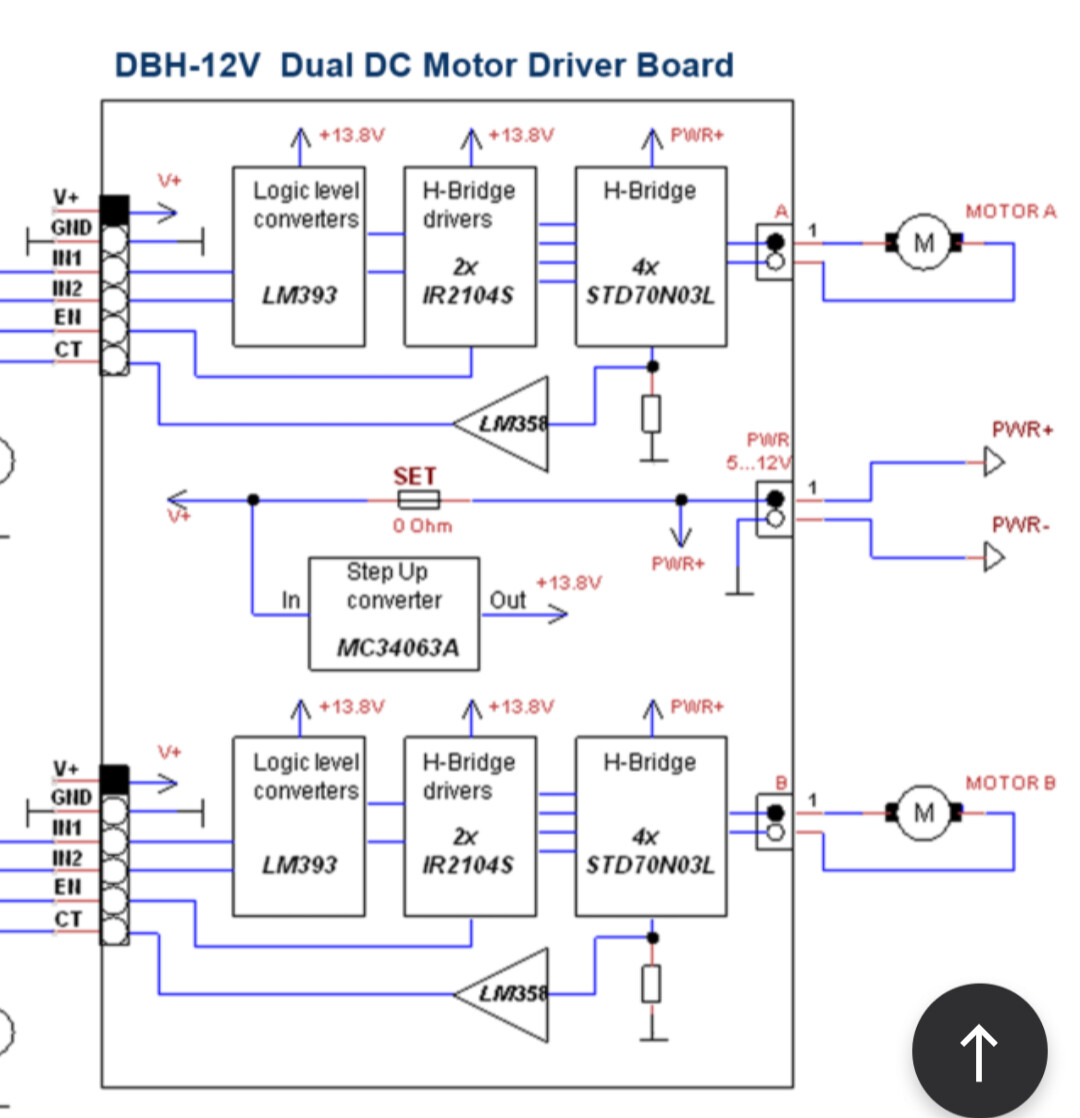
CT Output Voltage(V)=Current(A) x 0.155
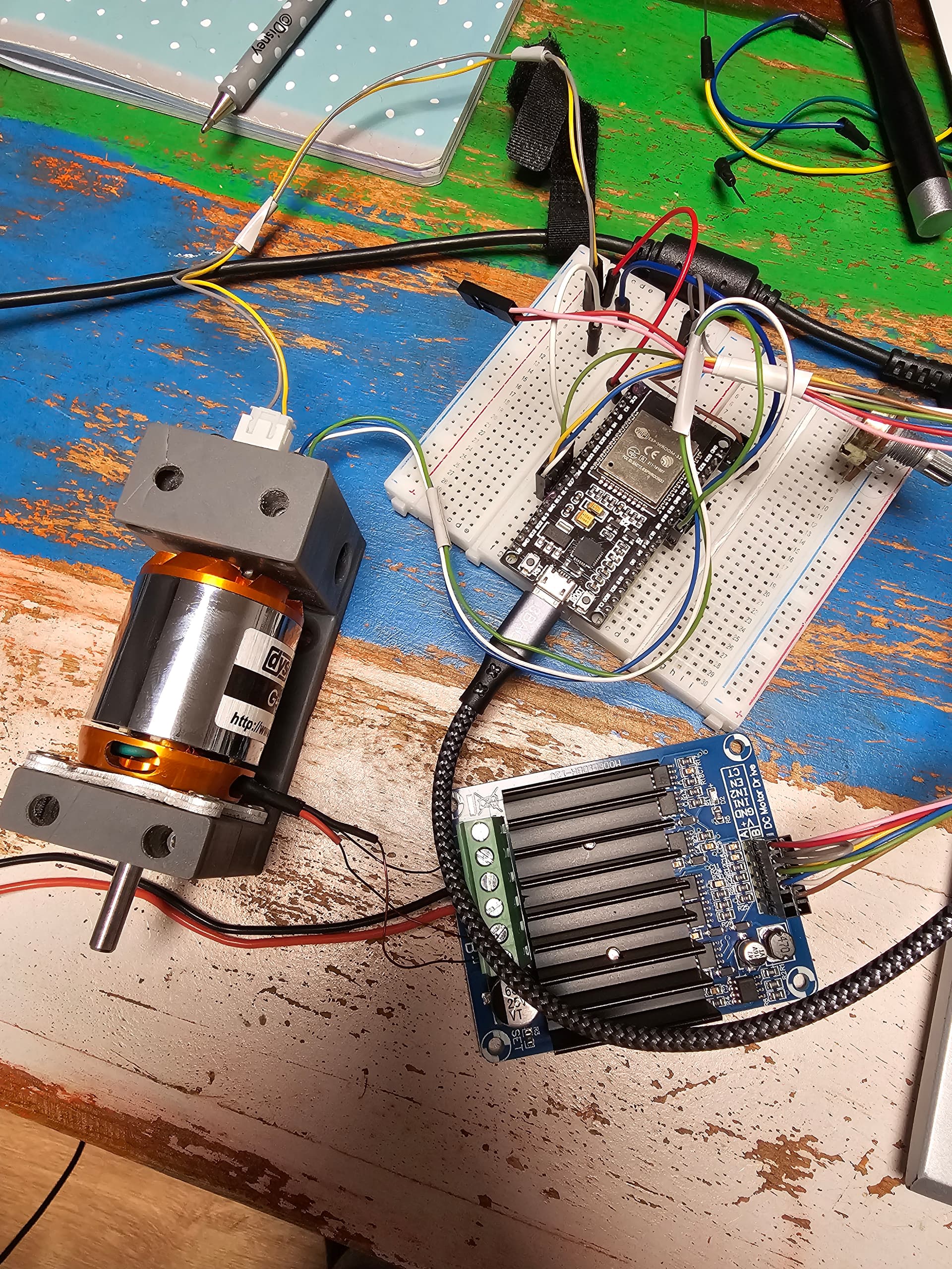
Just looking at getting some hardware to experiment with SimpleFOC and this board seems to tick all the boxes (affordable, high current, current sensing).
Looks nice! I wish they would post schematic. Depending on the parts it could also be a nice board for BLDC, if the 4 PWM inputs are really 4 half bridges.
FYI there is no current sensing for steppers (yet). There are a handful of people working on this at the moment, though.
Ah, so even if the current sensing was compatible with SimpleFOC, it wouldn’t work with a stepper? Was looking at steppers rather than BLDC motors as you get a lot more torque/$.
No, in theory you can do it, it’s just currently not implemented yet in simpleFOC.
As long as you can read something that linearly correlates with the current it could be used. I agree about the torque, I have recently been working on stepper projects as well!
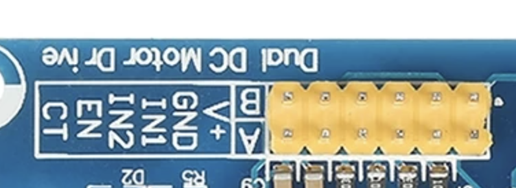
I only see In1 + IN2 on the header as input and the german translation says “Dual H bridge”
I’m sure its only suitable for one stepper or two brushed DC motors.
Yes, it really is. For stepper motor, you can use 4 pwm mode and for bldc motor, 3 pwm mode. A voltage divider is apparently needed to measure the current
I found a schematic for this driver. Apparently, the current meaning works for the channel. A shunt resistor is used on two half-bridges. That’s why I always get success: 2 when calibrating the current meaning. It is necessary to cut the track from the shunt resistor to one of the half-bridges.