I am currently facing to an issue related to a custom board I have designed similar to the simpleFOC Shield v2.0.4.
I am using a STM32F411CUE to drive up to 4 motors, but first I am only focusing on one. I have defined my phases and current input that way:
The problem is that I always get an error message that says “Init not possible, driver not initialized” and this is connected to the previous error “STM32-DRV: ERR: no timer on pin 18”.
The error message you’re getting is generated on line 450 of SimpleFoc src/drivers/hardware_specific/stm32_mcu.cpp, after calling findIndexOfFirstPinMapEntry, which references PinMap_TIM. After hunting that down (it’s in AppData\Local\Arduino15\packages\STMicroelectronics\hardware\stm32\2.2.0\variants\STM32F4xx\F411C(C-E)(U-Y)\PeripheralPins.c), it does not have an entry for PB_2, so that’s ultimately the source of your error.
PB_0 is TIM1_CH2N and PB_1 is TIM1_CH3N, so I’m guessing the other one you want is TIM1_CH1N, which is PA_7. That is pin 17.
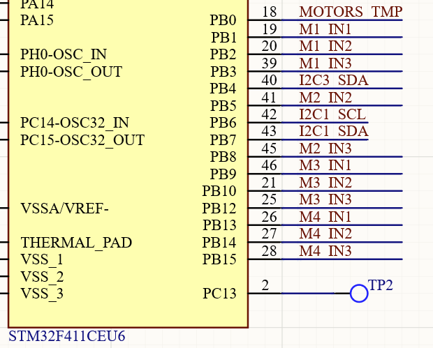
Another thing I noticed is that your schematic shows PB1, PB2, PB3 for for M1_INx, whereas your code uses PB0, PB1, PB2. But either way you have PB2 in there and it doesn’t have any PWM output.
Thanks a lot for this. I completely forgot to check whether PB_2 was available in the PeripheralPins.c file. I was also not sure that I needed a PWM output to these INx specific pins.
Is it ok to define these INx pins to any GPIOS as long as they have TIMx_CHx feature ?
I’m not sure. I’ve never programmed anything for STM32 before, so I’m not familiar with it’s particular PWM hardware. But I will be soon, either on B-G431B-ESC1 or Valentine’s Lepton board, so part of my reason for doing all that digging was to get familiarized with the library layout
That SimpleFOC function sounds like you can. I think TIM1 is specially designed for motor control, but SimpleFOC is probably just using it as another generic timer.
I have seen that the library works well with TIM2 and TIM3 when I tested it on a NUCLEO F411RE
(PC7 as IN1, PB4 as IN2, and PB10 as IN3).
I have checked my motor M4 (from the schematic above) that used PB13-/14/15 and it does not work either… Could you tell me why ? They are all on TIM1 but TIM1_CHxN.
I’ll say this again, without the full code and schematics it will be nearly impossible for others to help you. What you are asking is a really niche topic.
Running 4 motors off a single f411 is probably a bad idea. F411 has only one dedicated motor timer, the other seven are just general purpose timers. Also, from the very little you have posted, I can tell you have assigned 3PWM for the same motor on different timer channels. Some of your pin assignments don’t even have timers attached to them.
I hope you have not yet designed and fabricated the PCB, and are just in a discovery stage, else you need to go back to design stage and rethink everything from scratch.
Thank you Valentine. Of course I could share the schematic but you already guessed pretty much everything. Unfortunately I have already designed and produced the PCB.
I have to re-think the entire system since I would need a MCU able to drive 4 motors.
Concerning this below:
You have assigned 3PWM for the same motor on different timer channels.
I am not sure to really understand. For a 3PWM driver, do I need to connect the INx pins to the same timer but different channels or not ? I am asking because I have used a NUCLO F411RE with the following pins and it seemed to work well (IN1 - PC7 → TIM3-CH2, IN2 - PB4 → TIM3-CH1, IN3 - PB10 → TIM2_CH3).
You make me sad because designing and fabbing a pcb is a huge time and money commitment. Wish you had came here first and asked for help during the discovery phase.
You need one timer per motor, and they all have to be on the same positive side (no negative timers).
That won’t work. You are mixing timer 3 with timer 2. If it did work, it was just a lucky coincidence.
F411 just doesn’t have the computational power to drive 4 motors, and I’m assuming you don’t just need to drive the motors but also control them? So you need extra control logic which will consume MCU cycles, and you need angle/step sensors, and you need current sensing, etc? You will also need to communicate with the chip to send/receive commands/telemetry? That chip is way too small, not enough pins and not powerful enough to fit all that. Again, I wish you came here first during your discovery phase.
If you present your full use case, we may be able to give you some suggestions. One implicit assumption is that this is open/educational effort (you post your designs) and not a close commercial effort. I don’t know about others, but I don’t support closed commercial efforts for free, especially hardware PCB designs.
Can I ask why it is advised to use the dedicated motor PWM timers (TIM1 on the F411) to drive the motors ? What is the difference with another time that has the same specs and size (e.g. TIM3 or TIM4) ? Would it work as well ?