Alright, fixed a few traces, moved the ground pour to inner1 and pvcc to the bottom.


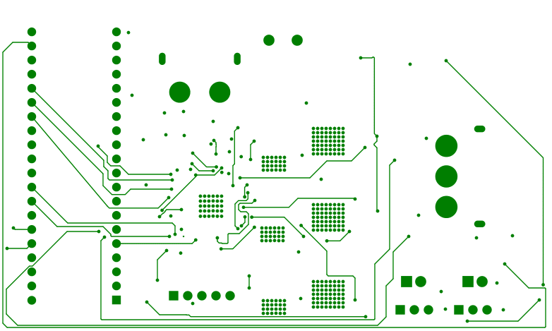


This newly added trace looks weird. Super close to its neighbor, and vias smaller than the others.

Also, the four traces running along the bottom edge of the board should be spaced out as much as possible, only going close together where pinch points around vias require it. Running side by side for a long distance like that is where crosstalk does become a real concern. Space them away from the traces on the top layer too, since they’re sharing the same ground plane.
EDIT: @Rikky is right, the LDO will burn up. I was off by a factor of 10 in my calculation before. 21.7V*35mA is 760mW, not 76. And most SOT-23 regulators say 200 or 250mW max, so the 500mW from DS8242-33’s datasheet is probably overly optimistic.
But let me ask a so trivial question, why do you need to design a board and still stick with one dev module as bluepill?


Hi kamilo,
Nice project, could you share a bit about the control and coding side with the C8T6? I want to ask if you plan to do current sensing on this board? If yes, what is your expected control loop frequency? Earlier I tried a similar setup like yours, with the C8T6 bluepill, AS5600, and the DRV8302, but the bluepill couldn’t handle current sensing and that slow AS5600 reading above 4kHz loop. I’m curious to see how your board’s performance would turn out.
Yes, Id be happy to, if I had much of a coding side of this worked out yet. Being designed for a robotic arm, i knew i wouldnt need all that much rpm so i havent really worried about the max loop frequency and am waiting to see that in practice. As for current sensing, yeah im planning to use it.
Ill be happy to share more once i actually find it out.
Yeah, 4KHz is probably about right. IIRC, my Leptons with 64MHz STM32G031 run around 5KHz, but that’s without current sensing. On 170MHz G431, I get around 20KHz without current sense and 16.5KHz with. So if we do 5*(72/64)*(16.5/20) we get 4.6KHz predicted loop rate. Probably fine for a robot arm.
Alright then, ill get ready to order the boards soon-ish.
Well then, the boards have finally arrived and in good shape. But of course problems have already shown up as well.
Probably should mention ive switched to blackpill f411 boards instead of the bluepill for the increased memory and clockspeed, nearly fully pin compatible and on the same stm32 architecture.
The first issue ive encountered was that even defining the 6pwm driver in the code soft locked the microcontroller, got around that by switching to 3pwm.
The current showstopper is that the motor cant seem to spin up on its own. The first thing i tried was the simplest possible setup, so open loop velocity control, and even there it failed to spin up on its own at all, and only managed to do so with a manual push at a single specific speed, depending on the pole number i set(conflicting info about this motors pp on the internet).
Ive tried to go further on to foc with a position sensor, for which the sensor itself is working fine, but the failure to spin up is, i think, causing foc initialization to fail.
And so i have to ask for help again.
My coding is not pretty at the best of times, and this is not a good attempt, so i apologize for the mess.
#include <SimpleFOC.h>
#include <SPI.h>
#define MOSI_DRV PB5
#define MISO_DRV PB4
#define CLK_DRV PB3
#define CS_DRV PB2
SPIClass spiConnectionDRV(MOSI_DRV, MISO_DRV, CLK_DRV);
// BLDC motor instance BLDCMotor(polepairs, (R), (KV), (L))
BLDCMotor motor = BLDCMotor(11, 0.28, 750, 0.14);
// BLDC driver instance BLDCDriver3PWM(phA, phB, phC, (en))
BLDCDriver3PWM driver = BLDCDriver3PWM(PA8, PA9, PA10, PA15);
// lowside current sense instance LowsideCurrentSense(R, gain, phA, phB, (phC))
LowsideCurrentSense currentsense = LowsideCurrentSense(0.0025, 10, PA0, PA1, PA2);
// commander instance
Commander command = Commander(Serial);
void doTarget(char* cmd){command.motion(&motor, cmd);}
void setup() {
// start serial
Serial.begin(115200);
spiConnectionDRV.begin();
spiConnectionDRV.setBitOrder(MSBFIRST);
spiConnectionDRV.setDataMode(SPI_MODE1);
spiConnectionDRV.setClockDivider(SPI_CLOCK_DIV8);
setDRV8305_3PWM();
// set power supply voltage
driver.voltage_power_supply = 12;
// set driver voltage limit, this phase voltage
driver.voltage_limit = 2;
// initialize driver
driver.init();
// link driver to motor
motor.linkDriver(&driver);
// link driver to current sense
currentsense.linkDriver(&driver);
// set motion control type to angle / postion openloop
motor.controller = MotionControlType::velocity_openloop;
// set torque control type to FOC current
motor.torque_controller = TorqueControlType::foc_current;
// set motor voltage limit, this limits Vq
motor.voltage_limit = 2;
// set motor velocity limit
motor.velocity_limit = 20;
// set motor current limit, this limits Iq
motor.current_limit = 1;
// current q loop PID
motor.PID_current_q.P = 3.0;
motor.PID_current_q.I = 100.0;
// Low pass filtering time constant
motor.LPF_current_q.Tf = 0.02;
// current d loop PID
motor.PID_current_d.P = 3.0;
motor.PID_current_d.I = 100.0;
// Low pass filtering time constant
motor.LPF_current_d.Tf = 0.02;
// use monitoring
//motor.useMonitoring(Serial);
// initialize motor
motor.init();
// initialize current sensing and link it to the motor
// https://docs.simplefoc.com/inline_current_sense#where-to-place-the-current_sense-configuration-in-your-foc-code
currentsense.init();
motor.linkCurrentSense(¤tsense);
// add command to commander
command.add('M', doTarget, "target");
command.verbose = VerboseMode::user_friendly;
//motor.monitor_variables = _MON_TARGET | _MON_VEL | _MON_ANGLE | _MON_CURR_Q;
_delay(1000);
}
void loop() {
// this function can be run at much lower frequency than loopFOC()
motor.move();
motor.monitor();
// significantly slowing the execution down
motor.monitor();
// user communication
command.run();
}
void setDRV8305_3PWM() {
uint16_t address = 0x02; // GATE_DRIVE_CTRL
uint16_t data = 0x4000; // PWM_MODE=01 (3PWM)
// Construct SPI frame: [0 (Write) | 5-bit address | 10-bit data]
uint16_t frame = (0 << 15) | ((address & 0x1F) << 10) | (data & 0x3FF);
// Send frame
digitalWrite(CS_DRV, LOW); // Select DRV8305
SPI.beginTransaction(SPISettings(1000000, MSBFIRST, SPI_MODE1)); // 1 MHz, Mode 1
SPI.transfer16(frame); // Send 16-bit frame
SPI.endTransaction();
digitalWrite(CS_DRV, HIGH); // Deselect
}
Hey kamilo,
The 5010 is a motor made for drones, so that thing would eat a large chunk of current. I say you should crank up the
to somewhere around 12V.
Edit: Also don’t forget to crank up the
to the same level. I think it’s time SimpleFOC combined these 2 methods into one, or made the voltage_limit method of the Motor class call the voltage_limit method of the driver class.
The issue turned out to be rather simple, as they often do. I still dont know what was wrong with 3pwm mode, but it caused 2 of the 3 phases to not switch over to negative, instead being either floating or positive. Doing some pcb surgery to connect appriorate pins and switching to 6pwm mode fixed the issue, and the driver is now working beautifully.
Thank you to everyone who helped me with this project, itll be a long time before i trully understand how yall get the motivation to spend so much time helping strangers, but i appreciate it all the same…
No single post here is really deserving of being marked as the solution, as so many of them contributed so much, so i cant really close the thread.
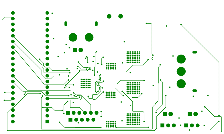
Alright then, screw the voltage regulator ill do an external one. I'll correct that and those traces and send the next version over.
– kamilo154