I’m designing a custom hub motor driver for e-bike and e-scooter applications for my project. The hardware design uses DRV8350H and CSD19536KTTT (following this reference- TIDA-010056 reference design | TI.com ), INA241A4 for inline sensing via shunt resistor, and STM32 Blackpill (STM32F411CEU6) for FOC implementation.
I am targeting 1.5-2kW motor (48V battery). 250W motor (36V battery) will be used for initial testing.
I am a complete beginner to driver design- I would really appreciate a review to eliminate any errors I have overlooked. Feedback on IN241A will be appreciated as well (I couldn’t find any previous projects using it)
I’m afraid I don’t have much time at the moment to look into people’s designs, so this is just based on a quick glance:
I’ll assume you have checked all the pin function of the F411 using STM32CubeIDE to make sure the pin assignments make sense. Motor PWM should go on TIM1 or TIM8, encoder ABZ should use CH1, CH2 of a timer for A & B lines, etc
The INA241 - I believe some filtering is recommended on its output?
AS5600 power does not look right, please check the datasheet and add the right capacitors
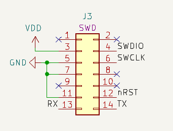
How do you plan to program/debug the STM32F411? I see no connections for either SWD or Serial? Add a STDC-14 header like in the picture below, then you can connect your ST-Link directly and have SWD and Serial for debugging:
if you plan to use stm32duino and SimpleFOC library you will need a board definition compatible with your board. Either you will have to create one yourself, or you can re-use an existing one like for BlackPill boards. But in this case you have to make sure you follow the design of the existing board for things like the USB, the external oscilator and its frequency, etc…
Ah, I think maybe you don't use the STM32 on your PCB directly but its just a header for an actual BlackPill board?
The provision of user-defined output filters is there in the evaluation module. Will include it in the design, although couldn’t find any recommended filtering for output.
Got it, will update accordingly.
Yes, this is the header for the BlackPill board. Thanks for the review!

Alright, will definitely add it. Thanks for the input!
– Saatvika