Hello SimpleFOC community! 
Context:
I have been following this problem statement of position control of a BLDC motor for a long time now.
I had tried a few methods to implement this, Earlier I tried making the H-Bridge using IRF44N mosfets and IR2103s gate drivers, but was unable to activate mosfets. After going through SimpleFOC shield V1, Infenion’s IFX007Tx board etc, I figured out that even if those boards have shortcomings, they are enough for my application.
Application: To be able to control speed and direction of Pancake BLDC motors of mid power ratings (500W or so)
Problems I am facing:
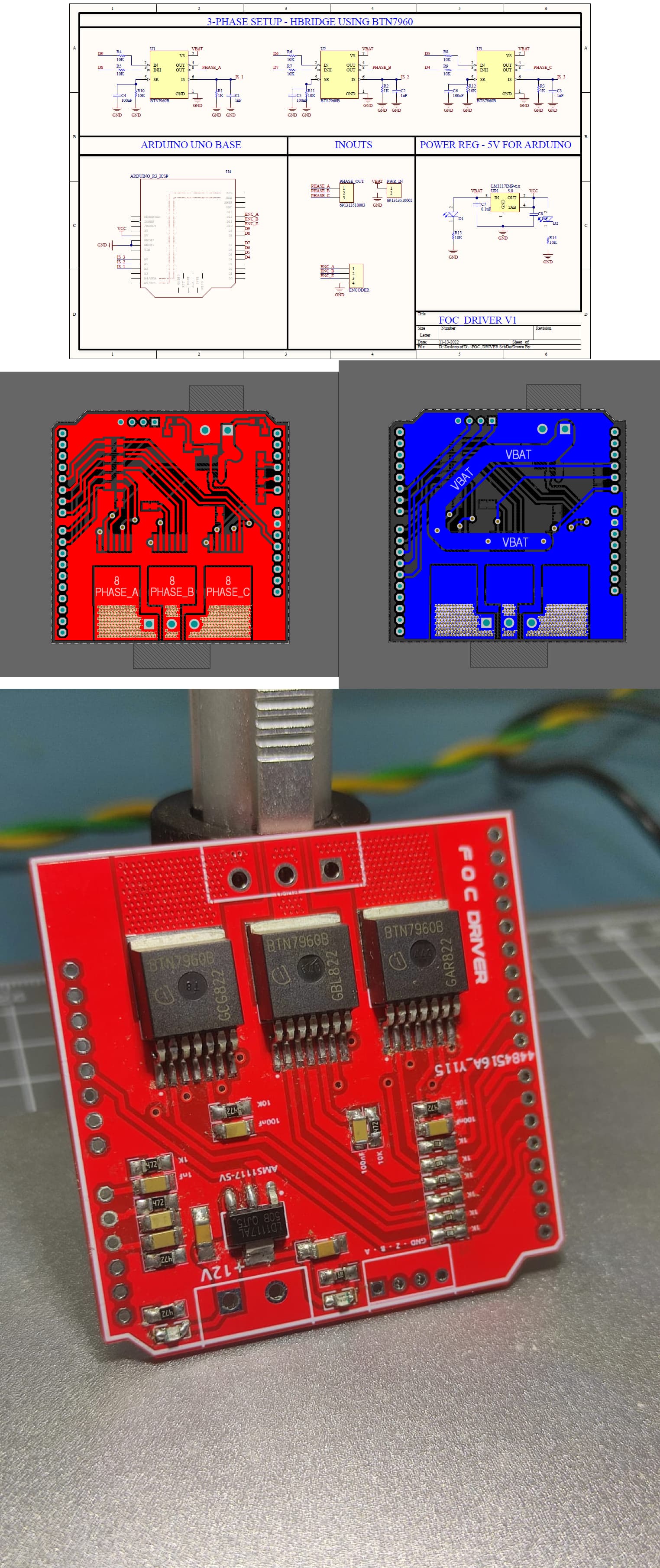
I have created a Design based on BTN7960B ics, by referring to V1 shield. Setup used a STM32F401 black pill development board as the MCU and In my setup I had connected all IN_H pins to 5V and used the IN_L input pins as my 3pwm input for the driver instance in the code. This design is tested on Open-loop position mode, The motor changed directions, moved with a certain speed and was not able to do a smooth low speed rotation, But all that can be possibly fixed with right tuning. This setup only worked on a current limited setup (I had a 1000mAH 1C 3S lipo battery powering the setup, It cannot provide larger current requirements).
When connected to a Good 50C 3S lipo, the BTN7960B heated up, Motor did not move at all and few of the ground planes on the PCB melted causing an open circuit. I was able to recreate this problem with a new board and completely new set of ICs
Are current limiting resistors required in this setup? If yes then wouldn’t that affect the power output I can deliver? Or is there any problem in the design itself? If someone can review my schematics it will be of great help!
Attachments:
- Schematic
- Board Layout Screenshots
- Snapshots of the final PCB
- Code used to test
- Link to the battery I have used
// Open loop motor control example
 #include <SimpleFOC.h>


// BLDC motor & driver instance
// BLDCMotor motor = BLDCMotor(pole pair number);
BLDCMotor motor = BLDCMotor(12);
// BLDCDriver3PWM driver = BLDCDriver3PWM(pwmA, pwmB, pwmC, Enable(optional));
BLDCDriver3PWM driver = BLDCDriver3PWM(PB3,PB4,PB5,PB13);

// Stepper motor & driver instance
//StepperMotor motor = StepperMotor(50);
//StepperDriver4PWM driver = StepperDriver4PWM(9, 5, 10, 6,  8);

//target variable
float target_position = 15;
float tick = 0;
// instantiate the commander
Commander command = Commander(Serial);
void doTarget(char* cmd) { command.scalar(&target_position, cmd); }

void setup() {

  // driver config
  // power supply voltage [V]
  driver.voltage_power_supply = 12;
  driver.init();
  // link the motor and the driver
  motor.linkDriver(&driver);

  // limiting motor movements
  motor.voltage_limit = 0.5;   // [V]
  motor.velocity_limit =1; // [rad/s] cca 50rpm
  // open loop control config
  motor.controller = MotionControlType::angle_openloop;

  // init motor hardware
  motor.init();

  // add target command T
  command.add('T', doTarget, "target angle");

  Serial.begin(115200);
  Serial.println("Motor ready!");
  Serial.println("Set target position [rad]");
  _delay(1000);
  tick = millis();
}

void loop() {
  // open  loop angle movements
  // using motor.voltage_limit and motor.velocity_limit
  motor.move(target_position);

  // user communication
  command.run();

  if(millis() - tick > 5000 ){
    target_position = -target_position;
    tick= millis();
  }
}
Battery used: https://robu.in/product/b-25c-1000-3s1p-deans/
Thank you!
Hello @Anirudha_Gaikwad
Welcome to the forum.
BTN7960B and the rest of the family such as IFX007Tx have a design limitation where the chip severely overheats at higher than 1kHz (1000Hz) PWM frequency. There are threads on this forum explaining the problem. Also, BTN7960 is an old design which performs even worse than IFX007Tx.
One way to solve your melting problem is to lower the PWM frequency down to no more than 3000 to 5000 Hz at most depending on your duty cycle, and put large heatsinks on the chips. Another way would be to use different drivers, which means you have to create a new board design with different components.
Cheers,
Valentine
I think ir2103 requires the low side input to be inverted compared to what simpleFoc outputs (low signal on LIN pin will produce high output on the low mosfet) - you would be better with ir2101 (they are pin compatible, you can probably just replace the gate driver).
For BTNs, lower PWM and hope you can live with the motor noise (I guess that will depend on the acoustics of the motor). Hoverboard motors on 3-5k pwm are extremely irritating, but I am using them for an outdoor aplication and I don’t mind the noise.
Thank you for explaining in detail.
I have the setup Infront of me and I tried lowering the pwm frequency of the driver instance, I went down till 500Hz, still the power cables tend to warm but a lot and I can see magic smoke from a few places (Mostly jumpers)
Is pwm_frequency the only problem in this design? It makes me wonder why did the setup run properly on a current limited environment.
I also checked the phase resistance of my motor, which is about 2Ohms, It coincidentally matches the datasheet load value. I checked if those ICs are going into error mode, but they aren’t. Without a motor they work just as expected, as soon as a load is connected things start to warm up 
Thank you for your response.
I understood that those gate drivers might not be a good way to go about it, I was basically recreating one of the high current boards mentioned in the guide, I found on Ebay(this one)
Gave up on it and thought I should try a simpler hardware in my first attempt, hence the BTN7960B
I have no problem with the noise if at all the setup works, lower PWM unfortunately did not help. I think something is wrong in my schematic itself, Can you please verify if the schematic seems right?
You need to redesign your circuit and especially the high current portion.
Yes understood the mistakes, I will correct them in my next design.
For now I think the only correction I can implement is changing the SR resistor to 0E. I will try this and update,
Thank you for the response, I will run the next design through community’s review in order to avoid any new mistakes.
I will still blow up because the single via for the input power is your limiting factor. Yoou cannot carry more than 1A with that via.
I replaced the SR resistors with 0E,
For the power copper problem, I did some dirty prototyping with 20guage wires (same as the ones used in the Pancake motor I am using)
Here is an image of the same (I know its still not the right method but as I said it is just some dirty prototyping to debug/verify the problem source to fix it in the next iteration)
This time the magic smoke came out of the motor, so I guess I have provided enough path for the current to flow from the PCB.
Very good, that looks a lot better.
I guess it’s part of your learning experience. But this is a good start. Please post more pictures and videos later when you make it work.
Cheers,
Valentine
Update:
I finally figured out the problem, (maybe?)::
STM32F401 blackpill board was not generating PWM as expected on the pins I used after I connected the high C battery, not sure why but replacing it with a Bluepill did the job.
Now I am at normal problems that everyone faces, Like motor noise, clogging, Tuning etc.
Observations: None of the BTN7960B heat up if I am below 3KHz, Motor warmed up quite a lot during the tests but I suppose that can be solved when I switch to Closed loop?
Here’s a video of the test:
Video
That’s about correct. But you will hear a lot of high pitch noise (I could even hear it on the video) and you will not be able to achieve high velocity, only low speed gimbal velocities. If you replace the slew resistors to 0 Ohm you may be able to increase to 5kHz, even 10kHz with very good heatsink cooling.
That is correct. With open loop velocity cannot control the current, it’s hardcoded by you.
Cheers,
Valentine
Next time, test the driver without connecting the motor. Set phase voltages and if the measured ones match the values you have set in the code, then connect the motor. I managed to see the magic smoke before figuring out the safe steps:
- test the driver only
Arduino-FOC/examples/utils/driver_standalone_test at master · simplefoc/Arduino-FOC · GitHub
- test open loop low voltage
Arduino-FOC/examples/motion_control/open_loop_motor_control at master · simplefoc/Arduino-FOC · GitHub
- test sensor only
Arduino-FOC/examples/utils/sensor_test at master · simplefoc/Arduino-FOC · GitHub
- test closed loop
- make it work properly
Since I anyway have to create a new design now, I was planning to switch to better hardware.
I checked prices of DRV83xx ICs, making a custom gate driver circuit using IR2101s seems to be cheaper and easy to recreate.
This might be a really wild thought but can I use L6234PD as a mosfet gate driver? In that way I can use wide range of external high power mosfets.
Yes, Magic smoke taught me well.
Thank you so much for elaborative steps, I will strictly follow this and save my precious electronics.
Absolutely not. You may want to read up on mosfet basics and 1/2-bridge theory before you attempt anything like that, else you may injure yourself. You must use a correct, dedicated driver.
Cheers,
Valentine