Hello! I started dealing with current sensing using my stspin32g4, platformIO, genericSTM32G431VB.json and i have some doubts I hope you can help me with
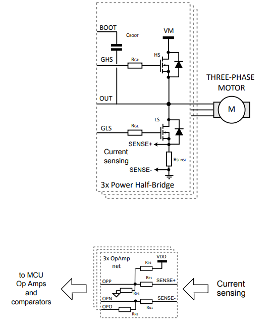
I’m using low side sensing, according to stspin32g4 datasheet:
I don’t know actually how to configure OPAMPS, i guess it should be some mode that uses all 3 pins (because I use external resistors working with opamp), but also obviously output should be connected to ADC channel. I dont see mode like that in CubeMX, am I right?
That resistors configuration provides half of voltage on output when there is no current, is it what library expect or is there possibility to write my own callback or sth to send current value?
I tried simply read some analog value and get 10 bits value, stm has 12 bits ADC, what can i do about it?
I think you can configure it… configure the op-amp, and then click on the pin. You should see an option like ‘ADCx INy +’ (with a plus). Choosing this should add the ADC input on top of the OPAMP configuration.
The library will calibrate the 0-offset on initialisation. So you can put it at any voltage you like. You should take care, of course, with the gain, to keep the voltage in range of the STM32s capabilities.
I believe the library will set 12bits, I have to check TBH. The library has its completely own ADC code, separate from Arduino analogRead(). When using Arduino analogRead() you can use setADCResolution(12); first to set the analog resolution.
So what you’re doing makes a lot of sense, but the library’s standard SMT32G4 current sensing code does not support the op-amps. You will have to configure them yourself.
If the current sensing will then just work without problems after you do the configuration, I don’t know, TBH. You will have to try it out, and it might turn out that you have to modify the library code a little bit.
You can also look at our current sensing driver for the B-G431-ESC1. We have a specific driver for this board because it uses the op-amps. Perhaps you can use or adapt this driver code.
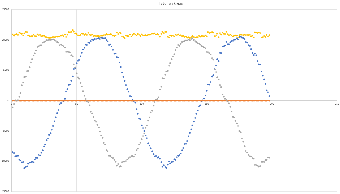
Would you like to take a look if something is wrong with the code? motor doesn’t move to target, in general behaves werid, sometimes jerks, vibrates, most time doesn’t move :F (velocity open loop works good)
How is the movement in torque-voltage mode? Be sure to set a voltage limit when testing!
Have you tuned the PIDs for velocity and angle control? You can’t jump directly from open loop to angle mode, you have to make sure torque-voltage mode is working well (this is the basic closed loop mode) and then the PIDs need to be tuned.
For current control you also need to tune the current PIDs…
What do you think about it? Would right pole pairs problem solve my troubles? After all torque, voltage controll should just rotate my motor right? Isn’t it confusing it looks a little like some angle controll??