Hi, I have DRV8302 development board, as5047p sensor, stm32f466re and 5010 motor. Does anybody try to realise current sensing on this board. It has embedded shunts. How can i use current control in SimpleFOC with this setup?
1 Like
Thank you for reaching out.
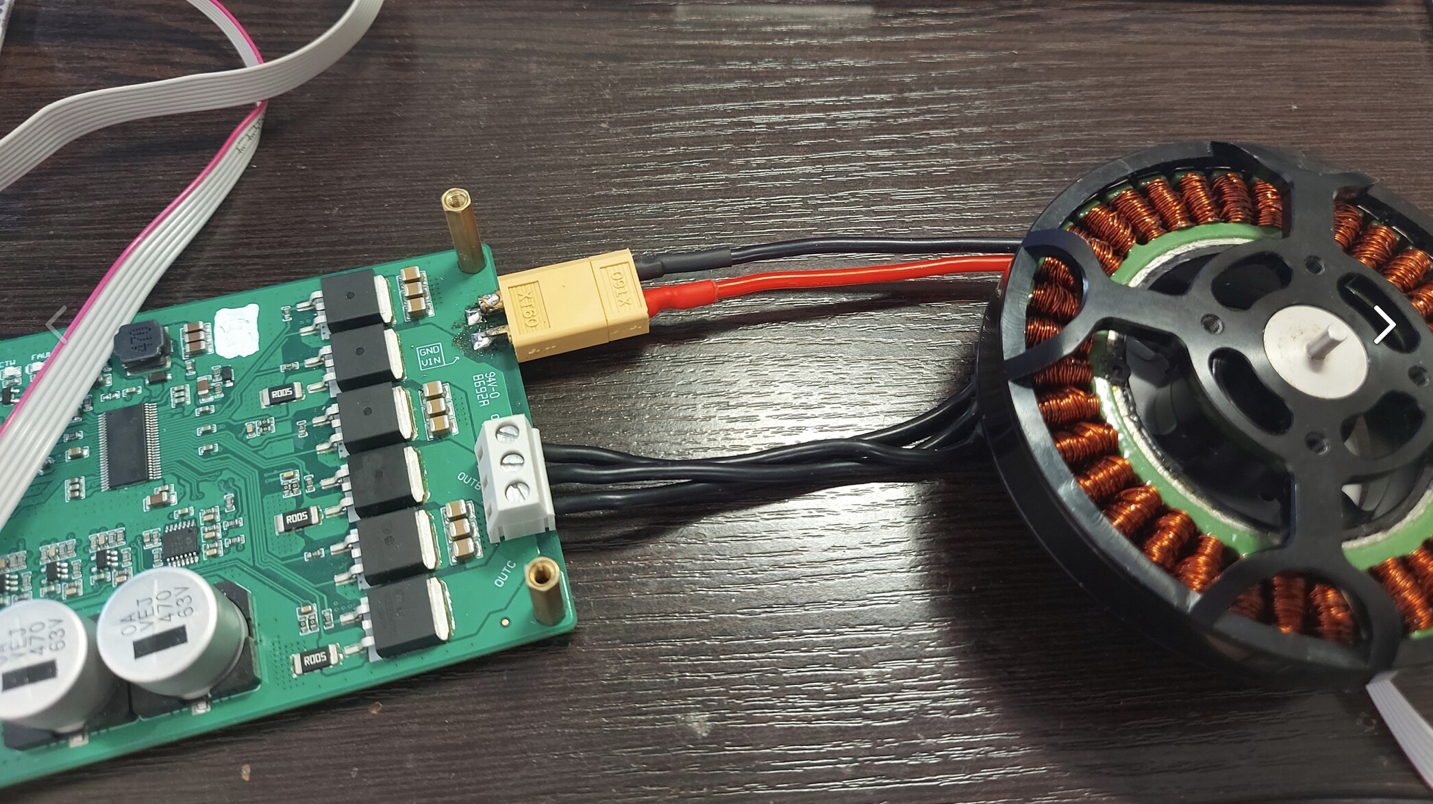
My French is a bit rusty, however, the board looks like a three-shunt low-side current sense. Let me check the schematics because the board has three shunts and the driver only two opamps.
Edit: It seems more like inline not low side.
Hard to tell without the schematics however the board looks like a three-shunt inline sense, and the designer had bypassed the driver’s opamps for current sense, so you may be lucky and can drive the board using inline current sense.
Please check the following link, there are examples.
Let us know how it goes.
I will also let others chip in I could be wrong.
Edit: Looking at the tracks the designer also output the driver’s two opamps current sense however without the real schematics this is a crapshoot because I am not clear which pins are those on the pinout.
Best would be run the board in a velocity mode and check the pins with an oscilloscope. Yes, it’s primitive but hey.
Hey @German_io and @Valentine,
It is an intersting idea to try to use this board as if it has the inline sensors, I dd not try it, but I’d be in to her how good/bad it would be ![]()
This board has three types of current sensing:
- 2x low-side opamp integrated in the DRV8302
- can be used with FOC
- 5mOhm shunt
- gain (20/40)
- 3x low-side opamps on the bord itseld
- can be used with FOC
- 5mOhm shunt
- gain 12.22
- 3x Back emf opamps + backemf circuit
- could be used for bemf control or sensorless
At the moment the library does not support the low-side current sensing but we are heavily working on it at the moment and we hope to be able to have it in standard release by the end of summer.
However, if you have a esp32 board, and if you are willing to downlaod the dev branch, then you’ll be able to do it. Esp32 has initial support for low side sensing and the baord we’ve tested it with is exactly the aliexpress board in the link.
You can find an example in the examples>hardware_specific_exampels>esp32_current_control_low_side:
The support is still in a very early stage and it is possile tha the api will chnage for the low side current sensing but if you are in to get to do some experimenting this implementation should be enough. ![]()
Thanks all you for support. Now I built balancing robot and it works in current setup but in the future I need to real current control for real torque control.
Today I haven’t esp32 but it simple to buy (and very cheap). I will test it soon. I’ll let you know the results
Which motor you use for tests ?
And simple question. How pwm fruequency influence to control? Is better fruequency to better performance ?
Nice, you have some video/imeges?
I’ve used a quiet large skateboard motor: N6354 180KV BLDC Amazon
Here is a video:
No not really. There is a trade-off there:
- The higher the frequency the more the motor is going to filter it and the more the motor will see only the average value of the pwm and not fluctuations in between
0-VCC. So in general the higher the pwm frequency the better. - Then there is the noise level, which is a bit equivalent to the no 1. the higher the frequency the less you hear it.
- Additionally, it is good the have at least 4-10 pwm periods per control loop (FOC) call. To give the time to the motor to “filter” the pwm signal.
- But the faster you switch the faster your mosfets need to be. Very high pwm frequencies introduce a lot of losses because your pwm period approaches the rise time of the mosfet. So you wish to leave the pwm frequency as low as possible, so that your mosfet rise time makes for a tiny portion of the pwm period.
- For low-side current sensing, you need to sync the pwm duty cycle and your adc measurement. And since the ADC measurent takes time and you need to ensure that the ADC measures only when all mosfets are off, we need to make sure that the pwm period is long enough so that this is possible. So for current sensing the lower the pwm frequency (the longer the period) the better.
So the rule of thumb is that without low-side current sensing (at least in the simplefoc) we try to have the pwm frequency in the range 20-25kHz.
And with low-side current sense, at least for esp32, I’d not suggest to go above 15kHz (20kHz max), which might result in a slight high-pitched sound. ![]()
I will share the photos and video when I build normal frame and design for my robot.
It good news this powerful motors with this board. In future I can build big and powerful robot with my standard setup. Thank you
Nice BLDC! Is it possible to smooth the motions out? I see it doing some nasty bumps. How smal increment’s are you able to make? I guess it means alot if there is resistance on the motor. Looking forward to see your setup. I have this pnp, with steppers. As you see, it is very accurate. Do you think a FOC controlled eboard motor could steer this, maybe with a 1 to 5 gear ratio. Or 7… The way I imagine, the pulley on the shaft should drive a belt with a larger gear/pulley. Usually these motors comes with 15 or 16 teeht pulley´s. So a 1 to 7 gear ratio would be 105 teeth, right. The 105 teeth gear drives a nother belt attached to the X and Y axis. This pulley could further reduce the gearing. Or you could use a custom teeth count (Eboard part) and calculate the teeth needed on the second belt pulley (3D printed)

Nice board with good specs.
Thank you for sharing.
So. Now I try to move big motor (8110) without current sensing, but it doesn’t move. It only some vibration and noise. How can I fix it?
Code is standard
/**
- Comprehensive BLDC motor control example using encoder and the DRV8302 board
- Using serial terminal user can send motor commands and configure the motor and FOC in real-time:
-
- configure PID controller constants
-
- change motion control loops
-
- monitor motor variabels
-
- set target values
-
- check all the configuration values
- check the https://docs.simplefoc.com for full list of motor commands
*/
#include <SimpleFOC.h>
// DRV8302 pins connections
// don’t forget to connect the common ground pin
#define INH_A PA8
#define INH_B PA9
#define INH_C PA10
#define INL_A PB13
#define INL_B PB14
#define INL_C PB15
#define EN_GATE PB3
#define M_PWM PB5
#define M_OC PB4
#define OC_ADJ PC8
// Motor instance
BLDCMotor motor = BLDCMotor(22);
BLDCDriver3PWM driver = BLDCDriver3PWM(INH_A, INH_B, INH_C, EN_GATE);
//BLDCDriver6PWM driver = BLDCDriver6PWM(PA8, PB13, PA9, PB14, PA10, PB15);
// encoder instance
MagneticSensorSPI sensor = MagneticSensorSPI(AS5147_SPI, 10);
MagneticSensorSPI sensor1 = MagneticSensorSPI(AS5147_SPI, 9);
// commander interface
Commander command = Commander(Serial);
void onMotor(char* cmd){ command.motor(&motor, cmd); }
void setup() {
Serial.begin(115200);
sensor.init();
sensor1.init();
motor.linkSensor(&sensor);
// DRV8302 specific code
// M_OC - enable overcurrent protection
pinMode(M_OC,OUTPUT);
digitalWrite(M_OC,LOW);
// M_PWM - enable 3pwm mode
pinMode(M_PWM,OUTPUT);
digitalWrite(M_PWM,HIGH);
// OD_ADJ - set the maximum overcurrent limit possible
// Better option would be to use voltage divisor to set exact value
pinMode(OC_ADJ,OUTPUT);
digitalWrite(OC_ADJ,HIGH);
// driver config
// power supply voltage [V]
driver.voltage_power_supply=24;
driver.voltage_limit = 3;
driver.pwm_frequency = 25000;
// driver.dead_zone = 0.05;
driver.init();
// link the motor and the driver
motor.linkDriver(&driver);
// choose FOC modulation
motor.foc_modulation = FOCModulationType::SpaceVectorPWM;
// set control loop type to be used
motor.controller = MotionControlType::torque;
// contoller configuration based on the controll type
motor.PID_velocity.P = 0.15;
motor.PID_velocity.I = 20;
// motor.phase_resistance=0.128;
// default voltage_power_supply
motor.voltage_sensor_align = 0.8;
// velocity low pass filtering time constant
motor.LPF_velocity.Tf = 0.001;
// motor.voltageRamp
// angle loop controller
motor.P_angle.P = 10;
// angle loop velocity limit
motor.velocity_limit = 20;
// use monitoring with serial for motor init
// monitoring port
// comment out if not needed
motor.useMonitoring(Serial);
// initialise motor
motor.init();
// align encoder and start FOC
motor.initFOC();
// set the inital target value
motor.target = 0;
// define the motor id
command.add(‘M’, onMotor, “motor”);
Serial.println(F("Full control example: "));
Serial.println(F("Run user commands to configure and the motor (find the full command list in docs.simplefoc.com) \n "));
Serial.println(F(“Initial motion control loop is voltage loop.”));
Serial.println(F(“Initial target voltage 2V.”));
_delay(1000);
}
void loop() {
motor.loopFOC();
// motor.move(sensor1.getAngle()*1.0);
motor.move();
// Serial.println(sensor.getAngle()*1.0);
command.run();
}
PS. Init() is ok
@Antun_Skuric, can you let us know if your motor can run for long time with drv8302 board with torque or velocity control. If so, can you share your test code ? I tested with a hub motor with torque or velocity control and it did run but only lasted for less than 30 seconds before it stopped by itself which I haven’t found out what causes that selfpause.
I have this problem to. I don’t know why it is.
With drv8302 my loop() stops itself
What is the maximum pover of this board you think? In description it 15amp without radiator and 45v. If will using radiator what max countinious power can i take?
What about STM32 does it support low - side current sensing ?