Controlling a Stepper Motor using two IBT-2 Half-Bridge DC motor drivers

Hi!

I am trying to run a big 12Nm NEMA 34 stepper motor using SimpleFOC with Arduino Pro Micro (Atmega34u4). Because of the high loads that this motor is going to withstand, I have chosen to use two high current half bridge DC drivers (IBT-2 or BTS7960), to drive each phase of the motor (these exact drivers were listed as options in the supported hardware section in the docs). My power supply is set to 25V.

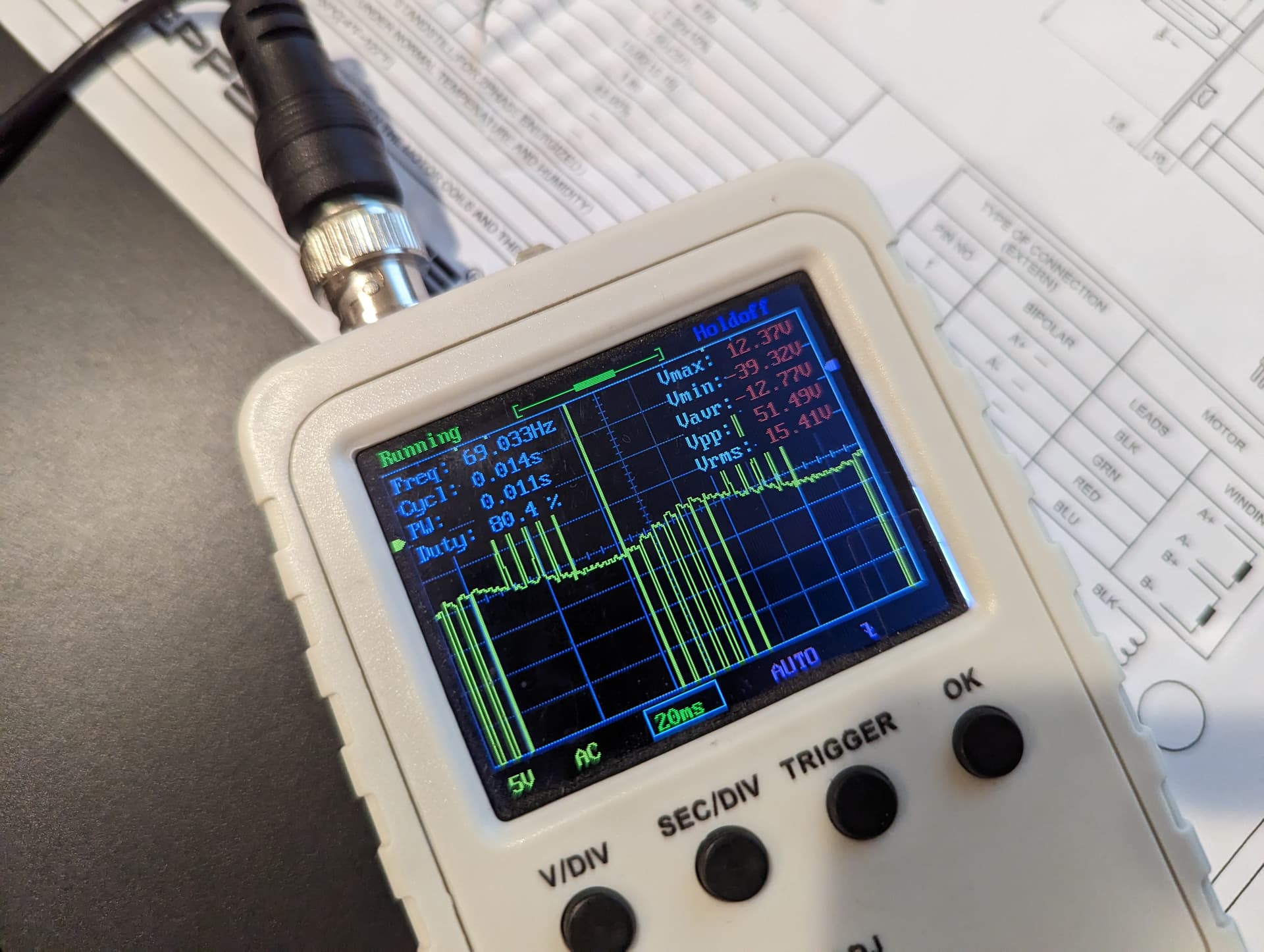
I have an encoder attached to the motor, but for now, I just want to run it in open-loop mode to be sure that the motor and drivers work together, however, I am having trouble doing that. I have tried setting every possible pin order in the driver constructor but I get similar results for all of them. The motor starts humming/buzzing and does not turn at all, however when I try to turn it by hand it resists. Here’s the code I used:

#include <SimpleFOC.h>

// BLDC motor & driver instance
StepperMotor motor = StepperMotor(50, 1);
// Stepper driver instance
StepperDriver4PWM driver = StepperDriver4PWM(6, 5, 9, 10, 4, 16);

// instantiate the commander
Commander command = Commander(Serial);
void doTarget(char* cmd) { command.scalar(&motor.target, cmd); }
void doLimitVolt(char* cmd) { command.scalar(&motor.voltage_limit, cmd); }
void doLimitVelocity(char* cmd) { command.scalar(&motor.velocity_limit, cmd); }

void setup() {
//  pinMode(4, OUTPUT);
//  pinMode(16, OUTPUT);
//  digitalWrite(4, HIGH);
//  digitalWrite(16, HIGH);
  // driver config
  // power supply voltage [V]
  driver.voltage_power_supply = 25;
  driver.init();
  // link the motor and the driver
  motor.linkDriver(&driver);

  // limiting motor movements
  motor.voltage_limit = 25;   // [V]
  motor.velocity_limit = 1; // [rad/s] cca 50rpm
  // open loop control config
  motor.controller = MotionControlType::angle_openloop;

  // init motor hardware
  motor.init();
  motor.initFOC();

  // add target command T
  command.add('T', doTarget, "target angle");
  command.add('L', doLimitVolt, "voltage limit");
  command.add('V', doLimitVelocity, "velocity limit");


  Serial.begin(115200);
  Serial.println("Motor ready!");
  Serial.println("Set target position [rad]");
  _delay(1000);
}

void loop() {
  motor.loopFOC(); 
  // open  loop angle movements
  // using motor.voltage_limit and motor.velocity_limit
  motor.move();
  
  // user communication
  command.run();
}

The drivers are connected like this:
Driver 1 (Phase A, Black (M+) and Green(M-) wires from the motor)

  • R_EN and L_EN to D16
  • RPWM to D9
  • LPWM to D10
    Driver 2 (Phase B, Red (M+) and Blue (M-) wires from the motor)
  • R_EN and L_EN to D4
  • RPWM to D6
  • LPWM to D5

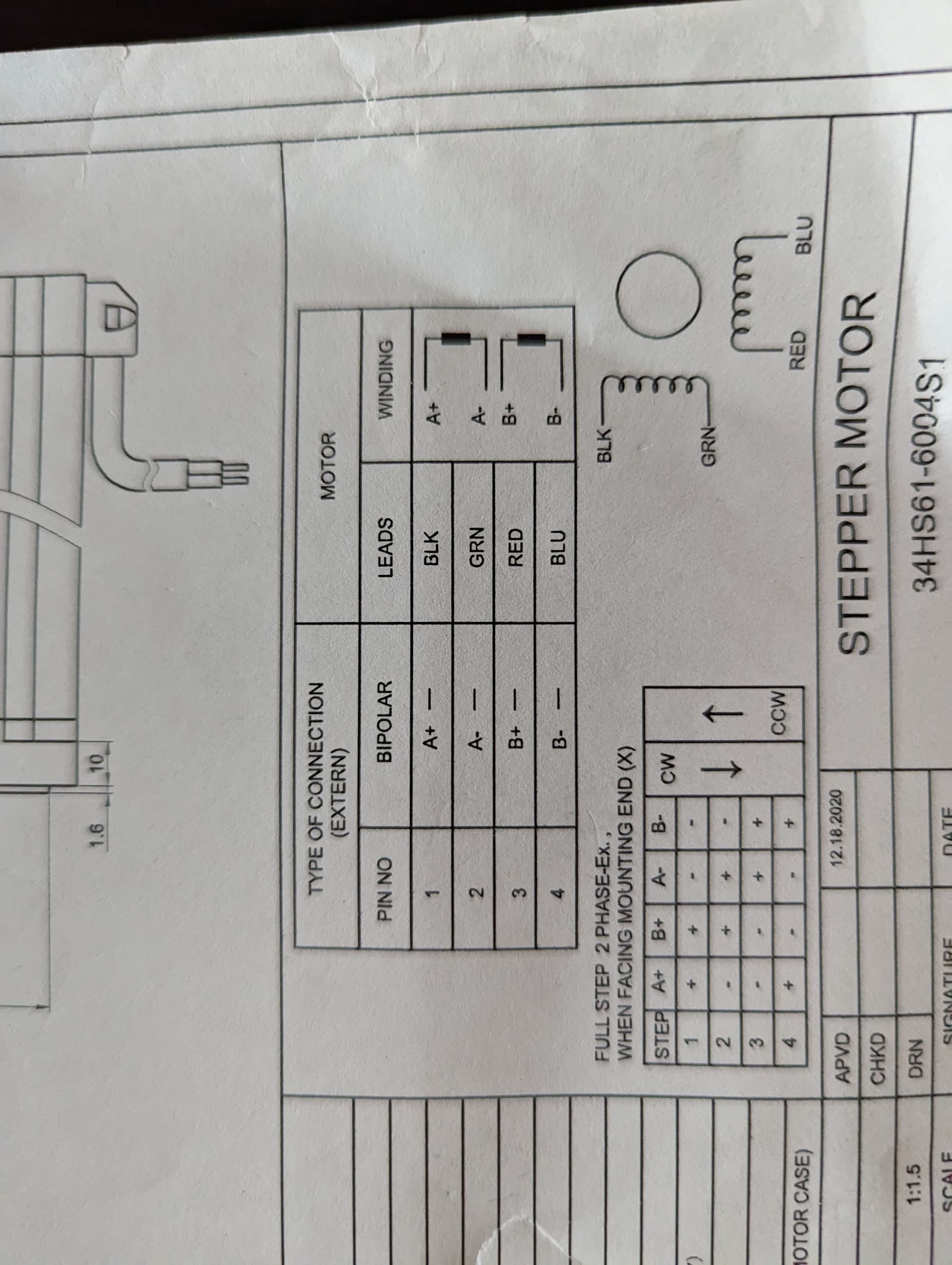
Here is a picture of the reference sheet for the motor (I think it’s a standard pinout).

Here is a link to a brief datasheet for the IBT-2 module.

Thanks in advance!

Hi @taron , welcome to SimpleFOC!

I am not sure what is up, but here a couple of things to try:

  • lower the PWM speed, the max supported by these drivers is 25kHz, but in our experience it needs to be lower than this…
    driver.pwm_frequency = 4000; // 4kHz

  • You’re using open-loop angle mode, so the expected behavior is that it will turn to a position and hold this position. If you change to open-loop velocity mode, and set a target speed (lets say 2rad/s) - does the motor then turn?

  • In open-loop mode you don’t call initFOC() or loopFOC(). The initFOC() can’t succeed because there is no sensor configured. Please comment out these calls.

1 Like

Hi,

Thanks for your reply! I tried decreasing the PWM frequency as you suggested, but I still get the same result. In the velocity mode, I still get the same result and the motor doesn’t turn. It starts making a buzzing noise with interruptions; seems like there’s certainly some signal and it wants to do steps but it can’t or the signal order is not correct. I guess that can happen because of incorrect wiring, but I tried every single order of pins with brute force and got no result.

Here is a video of how it sounds.

Did you adjust the voltage limit? Full 25v seems a lot

No. The motor is rated at 36V, but I saw people online running it on 24V. The driver’s max voltage is 27V so I decided to set the power supply to 25V.

You should definitely start low, especially in open loop. Try 3v to limit the current draw

driver.voltage_limit = 3;

Changing the voltage limit did nothing (I did not change the voltage of the power supply). However, I accidentally changed the driver.voltage_power_supply to 3, while I had driver.voltage_limit = 25; and the motor started shaking like crazy, but at the same time seemed to be turning.

Here you see how the voltage levels are restricted. Did you adjust the motor.voltage_limit accordingly?

Currently, I have it like this and I get the same result as in the video before:

  driver.voltage_power_supply = 25;
  driver.voltage_limit = 3;
  motor.voltage_limit = 3;   // [V]

I tried playing around a little bit with numbers. Strangely, I get any kind of movement (crazy shaking with little turning) when I set driver.voltage_power_supply = 3 (power supply is at 25V all the time). How should I play around and tune these numbers?

P.S. I am also thinking that I might have a wiring issue in the logical part although I am not sure. The wiring I am using is in the initial post and driver constructor looks like this StepperDriver4PWM driver = StepperDriver4PWM(9, 10, 6, 5, 16, 4);

Ok, good luck tracking it down.

So I changed the code a little bit, removed the driver and motor voltage limit, and started playing with driver.voltage_power_supply without changing the actual power supply voltage (25V). I started getting rotation on velocity_openloop mode when I set driver.voltage_power_supply around 6-8V. The motor is rotating but it shakes very hard. When I turn down the speed it starts moving abruptly.

Here is a video.

I took a look at the driver outputs of one of the phases and saw this:


They both look like this.

The sine has a lot of spikes and I think that causes the vibration. Also one of the drivers is heating up (the one connected to Red/Blue phase). I don’t know what that could possibly mean.

Hey,

Is that a current measurement or a voltage measurement we’re looking at? Voltage on one of the phases?

I’m not sure what is going on, but in setting the voltages has the following effect:

The driver.voltage_power_supply simply sets the “full scale” voltage for the software. It obviously can’t change the voltage provided by the PSU, so setting it to a value different from the “truth” simply has the effect of "scaling’ all the other values in SimpleFOC.
For example, if you set the driver.voltage_power_supply to 6V but the real value is 12V, then the “meaning” of all the other parameters in SimpleFOC is also divided by 2. So now if you set a motor.voltage_limit of 3V, it actually means 6V in real units.

Setting the PSU voltage and driver.voltage_limit to something fairly low for first tests is generally a good idea, you can always raise it up if needed.

So for your setup I would recommend setting:

driver.pwm_frequency = 4000; // these FETs like low PWM frequencies
driver.voltage_power_supply = 25; // the real value
driver.voltage_limit = 10; // lets start with a lower limit
motor.voltage_limit = 5; // generally, set the motor limit to 50% of the driver limit
1 Like

Hi,

In the photo, it is the voltage measurement. I spent the last couple of days experimenting with my setup, and still no success. It turned out one of the pin headers was not soldered properly, I fixed that and the behavior changed. The motor started vibrating back and forth (faster depending on the angular velocity) but still didn’t turn. My only goal right now is to make the motor turn. I tried multiple variants of wiring, with 2PMW and 4PMW driver configurations, but no result so far. I also tried playing with PWM frequency, PSU voltage setting, driver and motor voltage settings; it only changed how strong and loud the motor was shaking. Can anyone please provide a comprehensive wiring diagram and code setup to run this stepper motor with 2 BTS7960 driver modules? I am desperate at this point.

There’re many inaccurate datasheets for this module. I found this listing to describe all the pinout and driver’s behavior most accurately. Unfortunately, it is in Russian, but with page translation in Chrome it is readable.

By the way, it turns out that Arduino Micro’s 6th pin is not PWM capable, despite it being marked as such, which was another headache to discover.

P.S. - I also tried wiring the L298N driver exactly as shown in the demo video and with the same code but with this big motor, I still got the same result - a vibrating motor. The motor is rated at 36V but I am running 24V and that should not be an issue, as I tried using Pulse+Dir driver just to test if the motor is still turning at that voltage and yes, it does, at as low as 24V and 1.4 A.