Hey Guys,
I am happy to hear some proper control theory questions and remarques, I think that we dont have them enough. ![]()
This is true. The low pass filter is really not intended for smoothing the torque control dynamics (or making it more stable) but to filter the current values. And it is absolutely true that having the time constant around 0.1 is far to big and even strange to be working at all. (BTW the same is true for the velocity Low pass filter).
However, the low pass filters in the simplefoc are placed on the D and Q current not on phase currents so even though they are very crucial for the good dynamics they will not ruin the vector alignment. That is probably why such values even work.
In my opinion, whenever such solutions are necessary it means either one of the two things (which you also very nicely pointed out):
- PI gains are off and they need to be re-tuned ( lowered in most cases
 )
) - Current sensing is very noisy
Yeah recommending the gains is very tricky and as many of our users are using gimbal motors with higher phase resistance and lower currents many of our examples are using relatively high current control gains. And you are definitely right that we need a better way for tuning the current loops. For now we support the SimpleFOCStudio which can be used to find good parameters but its still hand tuning and requires at least a good idea of initial values.
I would really really like to automate the current control loop and I’ve been looking into some papers to determine the best ways and I hope to be able to do so soon. And I’m definitely open to any type of collaboration on this subject.
However, an important thing to say is that we are searching to find a general solution to these problems, not a solution which works on one board/driver/motor/etc. So this adds a lot of complexity to the problem definition and the way it needs to be implemented.
It is very likely that we will never be able to reach the performance of the STM or Microchip firmware for BLDC motors simply because we are choosing not to make our code so hardware specific.
The code for the BG431B board is actually a contributed code from our community
https://community.simplefoc.com/t/b-g431b-esc1-current-control/521
and the current sensing is very specific to this board. I personally do not even own one and did not test it at all.
The PWM/ADC alignment is done using injected channels and the code uses the integrated opamps in the STMG4 chip. There is probably room for improvement in terms of performance and we’d be happy to collaborate over this.
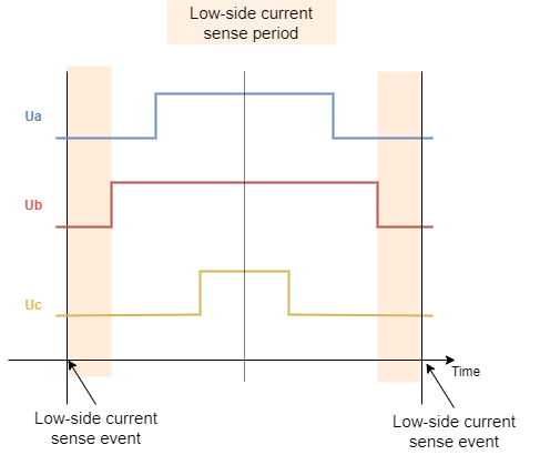
All of our stm32 based low-side sensing is based on the ADC injected channels and TRGO events that are triggering the ADC conversion exactly in the middle of the time the low-side mosfets are active (which is effectively the start of the center aligned duty cycle). This is not the most optimal synchronization technique, I think that the STM motor suite uses the fourth timer channel to trigger the ADC which will usually result in a bit more precise measurements. But at this point we decided not to use this option because we do not want to use additional timer channel for the ADC sync as the user might prefer to use it for something else. But this might change in future.
So at the moment, to avoid potential problematic situations due to the ADC conversion lasting to long and entering the high-side activation of certain mosfets we suggest using the PWM frequencies that do not exceed 20kHz. This in most cases results in behavior.
However there are many things that can be done to improve the low-side and inline current sensing implementation that we have currently. They are really in their early stage of developement. ![]()
This would once again be very very hardware specific. It is doable of course but at the moment the choices that we’re taking are oriented towards the cross-platform implementations more than to the optimal performance.
On the separate note, SimpleFOC loop times in the low-side current sensing mode are sometimes faster than the PWM frequency and the ADC conversion which means that effectively you get more than one update of the current target per PWM duty cycle. So we might be able to achieve the behavior you’re describing even without the interrupts.
The PWM and the ADC conversion is aligned for the low-side current sensing at the center of the low-side active interval. Here is the diagram.

As I said already starting the conversion at the center is not the best place to start the ADC conversion, it would be better to start it a bit before to be measuring the currents at the center of the all phases low part of the duty cycle. But as long as the timing is consistent and the PWM frequency is not too high the current measurements should be good.
Finally the current control in the simplefoc is at its early stage and I am not really happy with the results yet, I hope we will be able to improve its performance in the future. And we are open to any type of collaboration ![]()
Current control is complicated and requires some experience and having more control engineers onboard would be great!
We don’t actually. We only support the low-side current sensing for this board. This is a legacy issue because when the guys implemented the low-side current sensing on this board the library did not have lowsidecurrent sense interface so they used the inlinecurrentsense class. Later we’ve added the low-side current sense interface to the simplefoc and for this board we kept both implementations. So using inline or low-side current sensing interfaces will both use the same low-side code.