Hello, this maybe too much of a simple question but I been working on this conundrum for a long time without ay detailed knowledge of programming etc.
This is what I have managed to do. I have a JK42BLS01 motor which has hall outputs. I have managed to connect it to a couple of different BLDC controllers (BLD120A and a generic Chinese one).
I have uploaded Arduino code to an ATtiny 85 and can control the motor and run it at different speeds by generating a PMW signal. The only control I have is the ability to change the speed incrementally from 1 - 255 in the Arduino code. 1 being zero and 255 being 100% of full speed.
I can also connect the hall outputs to an Arduino Nano and can monitor the signals.
However, this is the controller that I am using:
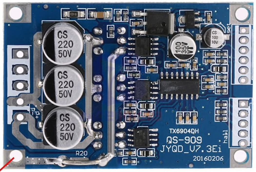
It is called : DC 12V-36V 500W PWM Brushless Motor Controller Motor Control Hall Motor. I have no other information other than it also accepts at PMW signal.
It doesn’t feature in the list of controllers on the community site.
It also has what is called a “Tachometer Pulse output”. I would assume that this is a square wave generated by the three hall outputs?
My goal is very simple. I would like to run the motor in a closed loop at a constant speed under differing torque loads.
The motor will be used to run a very old 35mm movie camera which needs to run at 25 frames per second (roughly 6250 RPM) with little or no variation in speed. This will then enable the camera to be used for synchronised sound shooting.
Would this be possible for someone who looks at Arduino code and has little to no idea why any of it works?
Here is a video of the motor running the camera at 2 frames per second using the board from a BLD120A BLDC controller. I’ve decided to use the generic Chinese one as it’s cheaper and smaller and seems to work just as well.

This is the code that I’m running on the ATtiny. I changed to Pin Configuration to make it work as the code was written for an Arduino Nano:
int PWM_Pin = 0; /* give PWM_Pin name to D3 pin */
// Perform initialization inside setup()
void setup()
{
pinMode(PWM_Pin,OUTPUT); /*declare D3 pin as an output pin /
}
// loop() executes continously
void loop()
{
analogWrite(PWM_Pin,255); / Produce 100% duty cycle PWM on D3 */
}
Any help would be gratefully appreciated.
Kind regards
Zynsk