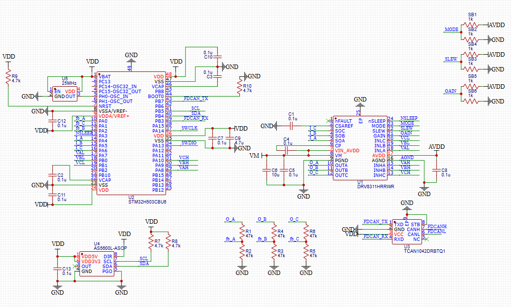
I’ve created the following CAD design, referencing various posts in the simpleFOC community, YouTube, and other blogs.
My desired function is essentially position control. However, since I’m already working on a 4-layer PCB, which is expensive, I’ve implemented it sensorless. I’ve added a back-EMF detection circuit and an FDCAN transceiver to enable high-speed control communication.
The back-EMF detection method will be implemented by generating an ADC signal at the end of the PWM signal and sampling the corresponding point.
The power supplied to the driver is as follows:
VM: 7.4V
VDD: 3.3V
To utilize the STM32’s SWD debugging feature, I need to add pull-ups to the signal lines. However, due to the limited space, I’ll have the downloader provide the pull-ups.
The DRV8311 gain, SLEW, and MODE settings are designed to be set directly with solder.
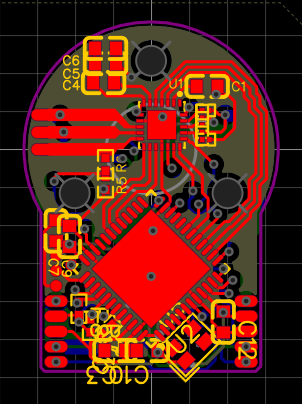
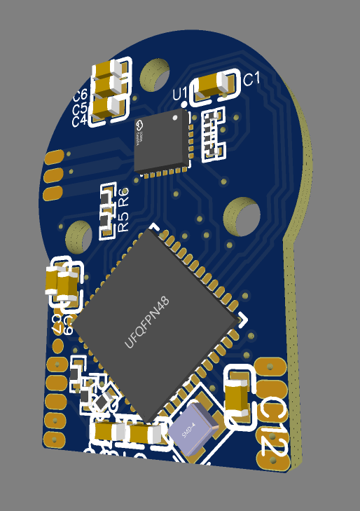
I’ve tried to avoid forming magnetic loops in the signals in the PCB artwork as much as possible, but since I’m not a professional, the layout isn’t perfect.
Please let me know if you have any suggestions for improvement.
2 Answers
2
Hi @flashgift80
I have a little bit of experience with the DRV8311 chip that you picked out. I have my own board and I also had some feed back on another board by Harry_Brenton. I think you might have an issue with the sleep pin on the DRV8311. If you want to used the LDO on the DRV8311 you need to wake up the chip from sleep first. The chip will not turn on the LDO unless it receives a signal on the sleep pin. In your schematic it looks like VM will go into the DRV8311 chip and then nothing will happen since the sleep pin is low. You’ll need to decide how to get the DRV8311 to wake up to supply power to the STM32. Hope this helps
That CAN transceiver needs 5V power. AFAIK all of them do. For interfacing with a 3.3V CPU like STM32, you need one with a separate VIO pin (typically in place of the NC pin on yours).
Your components are crammed too close together. Soldering problems are very likely, as their solder lumps will merge together and pull them out of position. The vias underneath small resistor pads are also likely to cause solder starvation and component movement. 0603 are generally ok with uncapped via-in-pad, but still preferable to avoid it.
Use STM32G431KBU3, it’s much smaller.
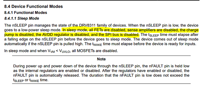
Thank you for your support! I knew that problem by that article so I already connect NSLEEP pin to MCU GPIO PA3. Also STM32 provide their power from external 3.3V, not DRV8311 LDO.
– flashgift80