Hello, I am looking to build a sim racing wheel using a hoverboard motor as they are cheap and mass produced and give surprisingly decent torque comparable to racing wheels thousands of dollars above their price point. My main concern with this project is that I am going to be controlling the motor moving to steer the car, and as such I am going to be fighting the motor and back driving it A LOT. I have seen other examples where people just hook up their Odrives to these motors and turn them into sim racing wheels. I am not fortunate enough to own one and I was wondering if there is a cheaper alternative that will do what I need without blowing up. I was looking into SimpleFOC but I am unfamiliar with this platform and I am unsure if it will be able to withstand what I need. Any help is greatly appreciated! Thank you all and have a wonderful rest of your day!
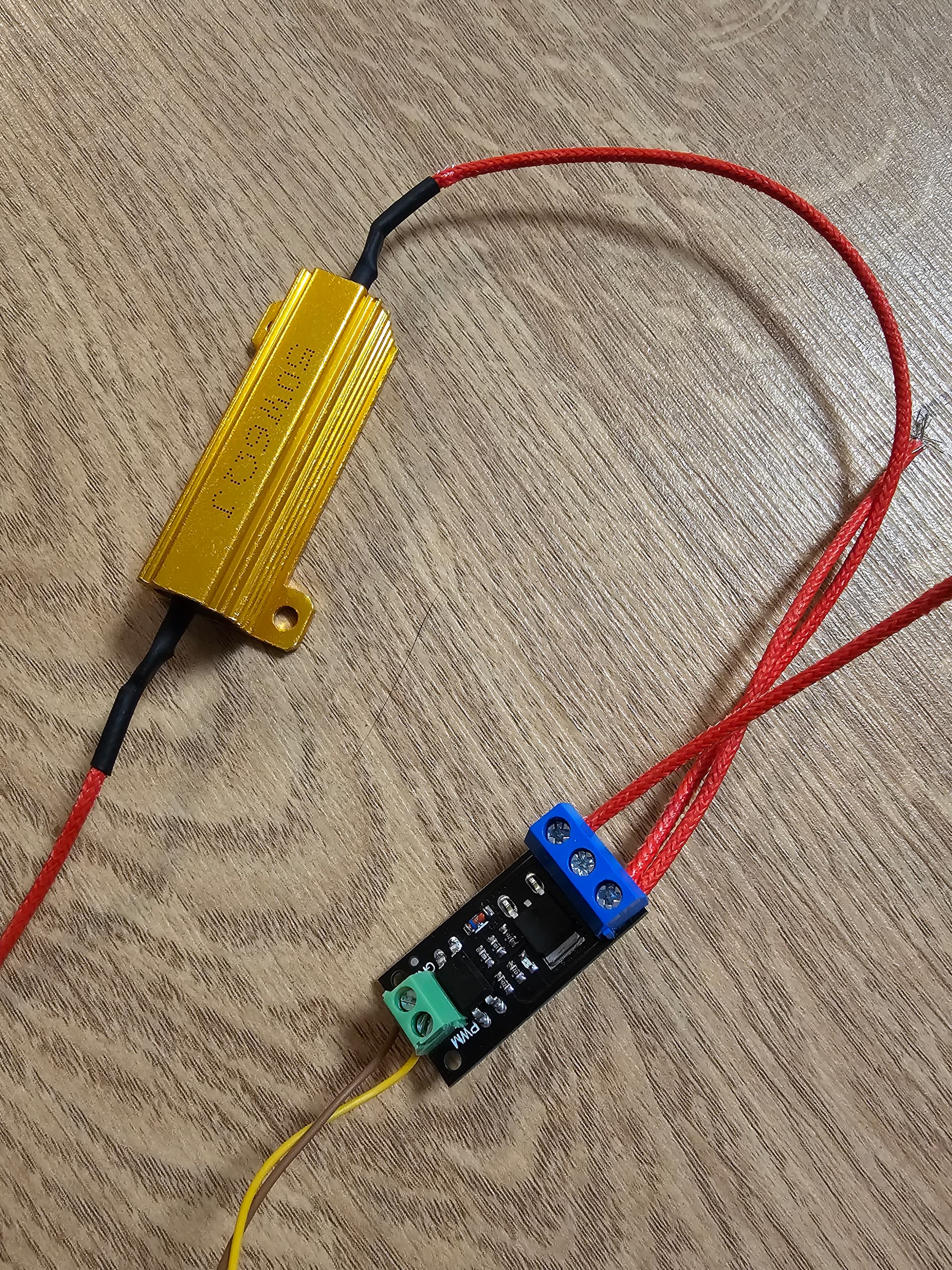
SimpleFOC does not have brake resistor support, but you could make a separate device to protect the power supply, which dumps power through a resistor if the bus voltage rises above a certain level. Valentine posted some designs in this thread https://community.simplefoc.com/t/protect-power-supply-against-bemf/2459/47
The easiest and cheapest way would be to buy a hoverboard.
They come with plenty of different controllers, but most of them could be hacked with sFOC.
Their hall sensors will not provide the smoothest feedback, you might want to add a magnetic sensor. (which can be tricky)
If you can also use the battery of the hoverboard, you won’t need the power-dump resistor mentioned above. But often the batteries of used hoverboards are dead… a replacement battery is around 50€.
I use an ideal diode to protect my PSU, so current doesn’t flow back to it.
What I noticed is that if I brake with no load, It draws less current from my PSU than my board’s normal idle consumption.
So I assume that some of that excess current is consumed by the board and can also go to the caps ?
That inspired me to answer a question I’ve been wondering about for a long time: Could you replace the sensors in a hoverboard motor with linear halls and use clarke transform to convert the signals to an angle?
The answer is: probably not. Too much saturation.

Nifty device! But probably not enough for a steering wheel. Repeated jerks back and forth could accumulate energy faster than it can dissipate and blow the capacitors or other components.
Another approach I’d like to get implemented in SimpleFOC is using the motor windings as a brake resistor. If you switch on all the mosfets of a single polarity, current circulates in the coils and resists motion. You can test it just by connecting the motor leads together without any driver. Hoverboard motors give quite a strong braking effect.
The problem is I don’t know how to calculate how much torque it will produce for a given PWM duty at a given RPM so the PID will still behave nicely when switching to this for negative torque. I think it’s linearly proportional to RPM and to PWM duty, so perhaps we can just add a variable that has to be manually tuned and calculate pwm_duty = target_torque / (shaft_velocity * tuning_variable). But I’m not sure exactly what the tuning procedure would be.
That’s what driver->setPwm(0, 0, 0); does.
It’s already there when disabling the driver, but should only be done at very low speed.
Yes, but that doesn’t prevent your power supply from being blown up when the velocity PID decides it needs to apply some torque in opposition to rotation ![]() I mean have loopFOC check if current_sp has the opposite sign from shaft_velocity and then calculate the PWM duty to produce the desired torque this way instead of calling setPhaseVoltage.
I mean have loopFOC check if current_sp has the opposite sign from shaft_velocity and then calculate the PWM duty to produce the desired torque this way instead of calling setPhaseVoltage.
That’s different.
Connecting the 3 phases together is like a passive braking. You can use it like a handbrake or close to standstill. (example from MESC)
Setting a torque opposite to the motion is regenerative braking.
You can calculate the dc current or measure it, and limit this current by limiting the torque.
Some of the Hoverboard controllers measure the dc current directly.
What I’m talking about is to call driver->setPhaseState(PhaseState::PHASE_LO, PhaseState::PHASE_LO, PhaseState::PHASE_LO) and then driver->setPwm with all 3 equal duty, calculated as proposed earlier. So the PWM cycle alternates between circulating current in the motor and freewheeling, controlling the amount of torque you get from the passive braking effect. As far as I know, the code to handle PHASE_LO and PHASE_HI is still only implemented for software 6pwm on STM32 and RP2040, as mentioned by runger in this thread https://community.simplefoc.com/t/regenerative-braking/2574/68
I’m not 100% sure that this wouldn’t just boost the reverse voltage even worse, due to the current path through the high side mosfet body diodes. I can understand pulsing high side alone for regen, opposing the reverse current and then releasing it to flow with boosted voltage, but pulsing low side I’m not sure. Does the current try to flow toward battery- and fail to get anywhere due to the low side body diode blocking it, or does it just go through high side body diode instead due to being alternating current?
Unfortunately the docs are not quite up to date on this topic, also because this feature isn’t 100% ready for prime-time ![]() But actually several more of the drivers have been updated to support phase state setting, including ESP32, Renesas and STM32 HW 6PWM.
But actually several more of the drivers have been updated to support phase state setting, including ESP32, Renesas and STM32 HW 6PWM.
I think to charge the battery you have to raise the voltage above the VBUS level. This is done by using the motor as a boost converter, but I assume its a bit tricky to do…
Otherwise, the difference should be how the inductors in the motor are discharged - if you short the low side, the current will circulate through the low side FETs with little resistance, and the motor’s BEMF is shorted out.
If you leave all the FETs closed the current has to circulate via the diodes, which is less efficient.
You can also actively control the decay, I suppose, by measuring the currents and enabling the correct FETs, perhaps like running the motor in opposition to the rotation.
There is a lot of confusion about the regenerative braking topic, I still think a torque opposing the movement will regenerate current.
But with a sim racing wheel, are we really talking about braking?
If you oppose the wheel’s movement, it will increase the q axis current, you will consume more, that’s still motoring, not braking.
I think I am wrong about this.
Is it possible to take such a thing? And use the voltage divider and ADC microcontroller to measure the voltage of the power supply. As soon as it starts to rise, open the mosfet with 1pwm and discharge the overvoltage to the brake resistor? Or use an op-amp
Yeah, we do need a brake resistor mode too. But for something like this steering wheel (or my hoverboard lathe spindle) the motor temperature isn’t an issue, so it would be nice to have a safe mode that doesn’t require extra hardware.
In fact, for a gaming steering wheel, relieving overvoltage with motor windings is a bad idea. The steering wheel is the only thing in the simulator that lets us know how good the grip of the tires is. When the car goes into a skid, the steering wheel becomes empty and we try to catch the car with quick movements of the steering wheel. And if at this moment we short-circuit the windings of the motor to relieve the overvoltage, then the engine will become heavy and we will get a tactile misconception of what is happening on the track. And of course, our car will fly into the bump guard, perhaps even grabbing an opponent))))
That’s why you need to be able to calculate the amount of braking torque it will produce and PWM the FETs between braking and freewheeling.
The question is whether freewheeling (all FETs disabled) will still cause overvoltage due to the body diodes? The more I look at the this diagram, the more I think the answer is yes. Even with all FETs disabled, current can flow from battery-, through a low side body diode, through the motor, through a high side body diode, and to battery+. So my dream is probably impossible ![]()

There’s also the option to commutate the motor with d-axis current to waste energy without producing torque. But that probably needs current sense, and I want something that works even with the most basic hardware.
I think this thread has wandered away from what OP (@starslayer) asked. He wants to know what else he could use instead of a an expensive odrive to drive a hoverboard motor.
A racing wheel sim (I’m guessing) doesn’t need to break your arm off so the torque requirements probably aren’t that high.
Personally I’d start with a simplefoc mini paired with any mcu you have to hand. A 5v tolerant mcu mighty be useful as i suspect the hall sensors require being pulled up to 5v.
The mini uses a drv8316 chip which includes the mosfets in silicon, it can therefore only do 2.5A current. But i think this is probably enough for a bit of feedback and juddering for sims. From memory the hoverboard motors phase to phase winding resistance is about 1 ohm (or is it a bit more like 3ohms?). Assuming you used a 12v supply your probably want to set a voltage limit of 2v.
Alternaively, the normal simplefoc board has a L6234 driver which can handle a bit more current so that is another option. That would be paired with an uno or nucleo mcu.
Or if you don’t mind doing fiddly/difficult soldering you might want to look at the B-G431B-ESC1 which includes an stm32g4 mcu + beefy external mosfets (more torque).
In summary i think you should ask yourself how much torque do you really need if it is “not much”, then you have loads of options and could start with a 10euro simplefoc mini. Btw there are cheaper clones of simplefoc board, if you can find a third party supplier you trust.
Owen is right and perhaps we should start our own thread for the braking topic.
There is also this thread here: https://community.simplefoc.com/t/regenerative-braking/2574/87 where we have been discussing the topic in the past…